Controllable passive artificial knee

Active Publication Date: 2015-06-25
RGT UNIV OF CALIFORNIA
View PDF9 Cites 63 Cited by
  • Summary
  • Abstract
  • Description
  • Claims
  • Application Information

AI Technical Summary

Benefits of technology

[0007]The present invention is directed to exoskeleton systems which include at least an exoskeleton knee with controllable resisting torque. In particular, the invention here describes an exoskeleton knee and its applications in a variety of exoskeleton systems where friction forces between two surfaces are used to impede the knee flexion and extension motion in various phases of a walking cycle. By controlling the friction forces between two surfaces, arbitrary resistive torques for the exoskeleton knee during some portions of the locomo

Problems solved by technology

This locked posture results in patients' ability to ambula

Method used


Image

  • Controllable passive artificial knee
  • Controllable passive artificial knee
  • Controllable passive artificial knee

Examples


Embodiment Construction

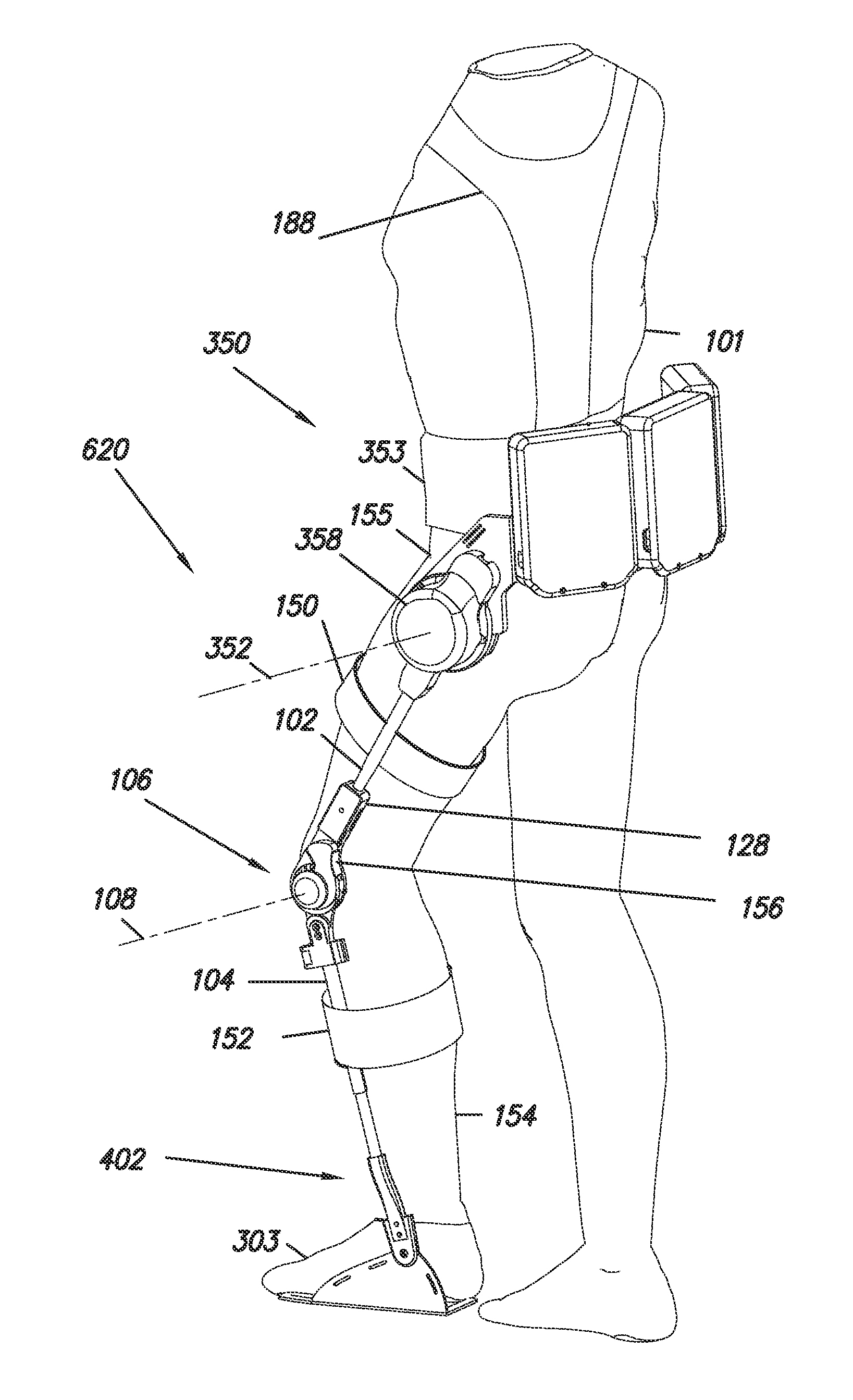
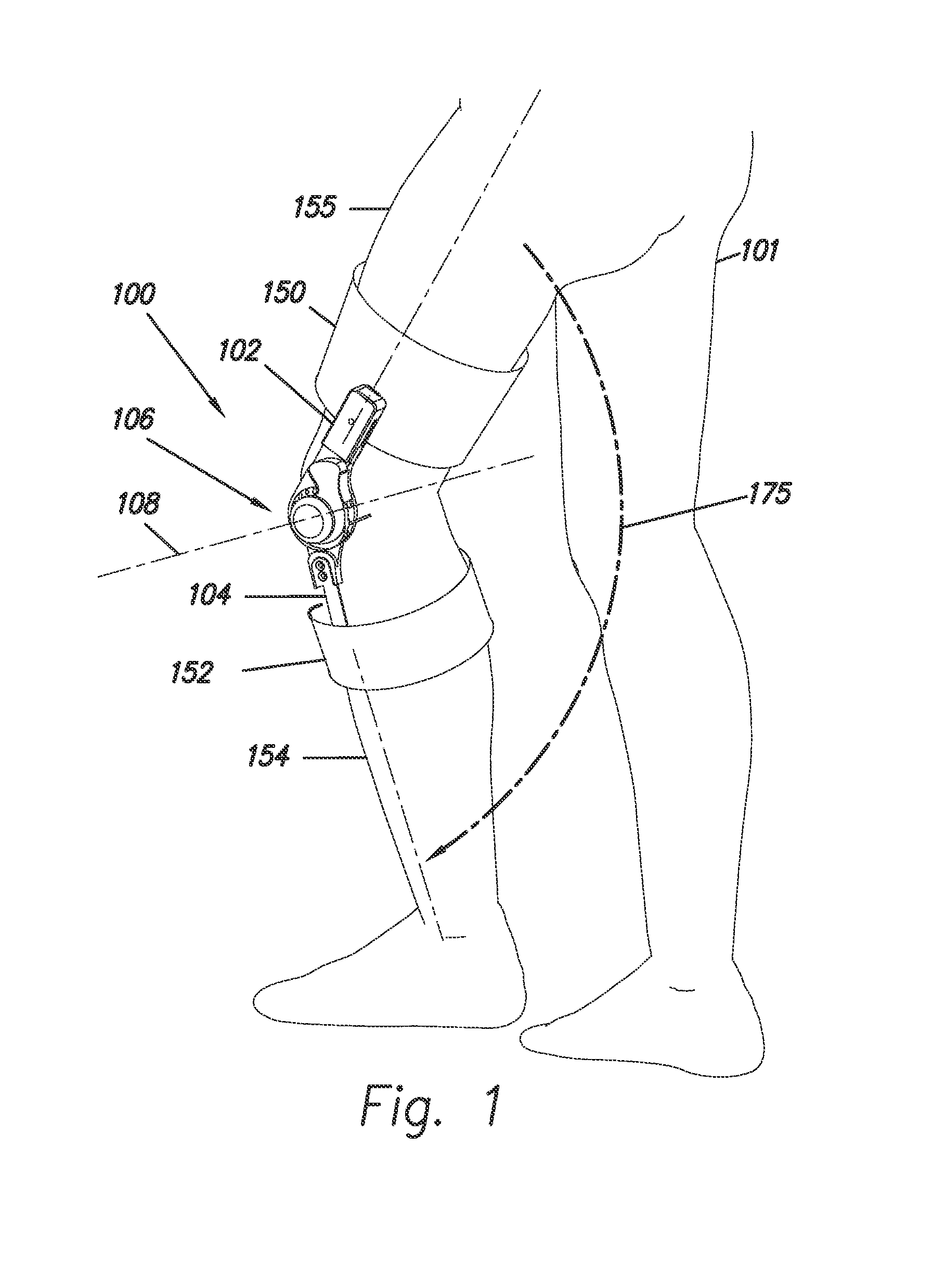
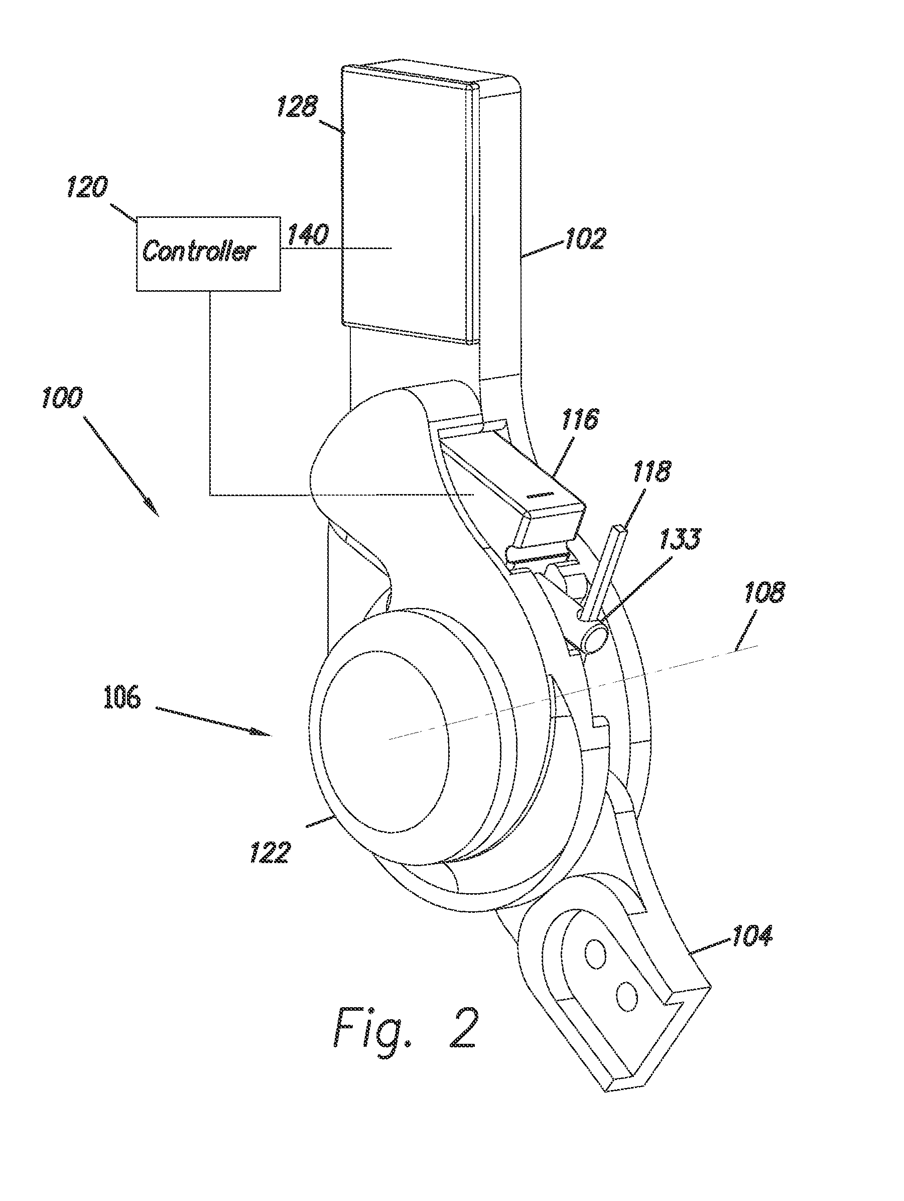
[0036]FIG. 1 shows an embodiment of an exoskeleton 100 which is coupled to a user 101. Exoskeleton 100 comprises a thigh link 102, a shank link 104 and a knee joint 106 configured to allow flexion and extension rotations between thigh link 102 and shank link 104 along a knee axis 108. Extension rotation indicates the motion of shank link 104 and thigh link 102 when shank link 104 and thigh link 102 move away from each other. Arrow 175 shows the direction of the extension movement of shank link 104 relative to thigh link 102. Flexion rotation indicates the motion of shank link 104 and thigh link 102 when shank link 104 and thigh link 102 move close to each other. In some embodiments of the invention, exoskeleton 100 further comprises a thigh connector 150 that allows coupling to a user's thigh 155. In some embodiments of the invention, exoskeleton 100 further comprises a shank connector 152 that allows coupling to a user's shank 154. In some embodiments of the inventions thigh connec...


PUM


Abstract

An exoskeleton (100) adapted to be coupled to a lower extremity of a person includes a thigh link (102), a shank link (104) and a knee joint (106) allowing flexion and extension between the thigh and shank links (102, 104). A torque generator (156) connected to the knee joint (106) includes a wrap spring (110) having a first end (112) coupled to the thigh link (102), and a second end (118) coupled to an electric actuator (116) capable of selectively positioning the second end (118) of the wrap spring (110). A controller (120) causes the electric actuator (116) to position the wrap spring (110) to provide a selective torque between the thigh and shank links (102, 104) based on a signal (212, 214, 216) produced by a sensor (164, 166, 168).

Description

TECHNICAL FIELD[0001]The present invention pertains to the art of artificial lower limb prosthetics and orthotic systems: more particularly, to an exoskeleton knee that can be used for a variety of orthotic applications.BACKGROUND ART[0002]A traditional knee-ankle-foot orthosis (KAFO) is used to increase the patient stability during the weight-bearing phase of walking. A traditional KAFO locks the knee in full extension, which provides stability. This locked posture results in patients' ability to ambulate with gait deviations that can lead to overuse injuries. A stance control orthosis (SCO) allows the knee to flex during the swing phase of the gait cycle and prevents knee flexion for stability during the stance phase. By allowing the knee to bend during the swing phase, SCOs allow a more natural gait, which may reduce secondary complications from gait compensations and allow the patient to walk with less effort. There are several stance control orthoses (prior art).[0003]Fillauer ...

Claims


Application Information

Patent Timeline
IPC IPC(8): A61F5/01
CPCA61F5/0123A61F5/0125A61H3/00B25J9/0006A61F2005/0158A61H1/0244A61H2201/0165A61H2201/1215A61H2201/163A61H2201/1642A61H2201/165A61H2201/5007A61H2201/5069A61H1/00A61H1/001
Inventor KAZEROONI, HOMAYOONTUNG, WAYNEHYUN, DON JINMCKINLEY, STEPHENJEONG, YOON JUNG
Owner RGT UNIV OF CALIFORNIA
Why Eureka
Try Eureka