Welding wire conveyor roller and feeding device for conveying welding wire

a technology of welding wire and conveyor roller, which is applied in the direction of welding equipment, arc welding equipment, manufacturing tools, etc., can solve the problems of misadjustment and inability to use the welding plant productively

Inactive Publication Date: 2015-06-25
FRONIUS INTERNATIONAL GMBH
View PDF63 Cites 8 Cited by
  • Summary
  • Abstract
  • Description
  • Claims
  • Application Information

AI Technical Summary

Benefits of technology

[0010]It is an object of the invention to provide an above-mentioned welding wire conveyor roller and a feeding device for conveying a welding wire by which it is possible to improve the conveying properties even with different welding wires, and with a simple construction at the same time.
[0012]The elastically deformable area of the welding wire conveyor rollers may be formed by recesses. These recesses and / or clearances in the welding wire conveyor rollers cause the desired deformation in the case of radial pressure load, by which it is possible to optimally clamp and convey the welding wire, depending on the diameter and on the consistency. Since two equal welding wire conveyor rollers are preferably used, the required share of deformation will be distributed equally to both welding wire conveyor rollers. The center of the welding wire will remain unchanged at the same position between the two welding wire conveyor rollers both when thin and when thick welding wires are used. This is of importance insofar as the welding wire may enter centrally in a following guide sleeve or the like without friction and without damage or deformation after leaving the pair of welding wire conveyor rollers.
[0017]The object according to the invention is also solved by a feeding device for conveying a welding wire, wherein at least one welding wire conveyor roller comprises an area elastically deformable in the radial direction between the running surface and the receiving aperture, and wherein the welding wire conveyor rollers are pressed against each other and / or against the welding wire by the receiving pins. Due to the at least one welding wire conveyor roller with the elastically deformable area it is possible to achieve optimum conveying properties since the welding wire can be clamped across a larger area and since hence no punctual forces occur. Likewise, it is possible to convey welding wires with different diameters or cross-sectional shapes with this feeding device without manual adjustments being necessary and waiting times for adjustment or change of the welding wire conveyor rolls occurring. The omission of a changing process of the welding wire conveyor rollers as well as of a manual adjustment of the optimum pressure is altogether a substantial simplification and a considerable saving in time. Further advantages may be taken from the above description of the welding wire conveyor rollers.
[0020]Advantageously, the receiving pins are, in correspondence with the design of the receiving apertures of the welding wire conveyor rollers, designed to taper to the free ends thereof, preferably to be cone-shaped. This makes it easy to slip on and press the welding wire conveyor rollers against each other.
[0023]The distance of the receiving pins relative to each other is preferably fixed. For an optimum adaptation of the contact pressure on the welding wire it is of advantage if the welding wire conveyor rollers mounted in the feeding device comprise a deformation even if no welding wire is arranged between them. This is achieved in that the sum of the radii of the unloaded welding wire conveyor rollers is larger than the center distance of the receiving pins.

Problems solved by technology

During this time it was not possible to use the welding plant productively.
In the case of a manual adjustment of the contact pressure there is also the risk of misadjustment caused by a selection of the parameters which is not optimal.

Method used


Image

  • Welding wire conveyor roller and feeding device for conveying welding wire
  • Welding wire conveyor roller and feeding device for conveying welding wire
  • Welding wire conveyor roller and feeding device for conveying welding wire

Examples


Embodiment Construction

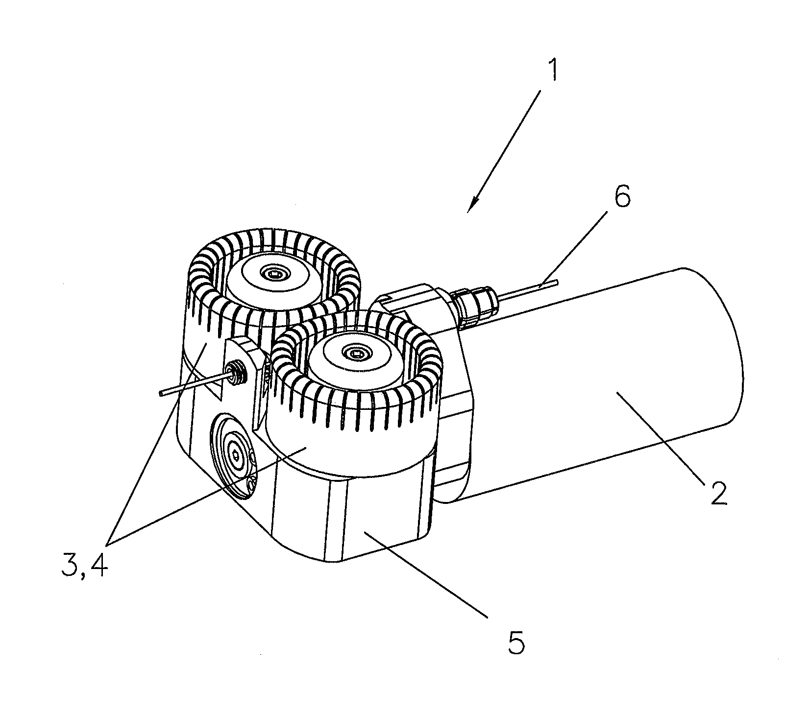
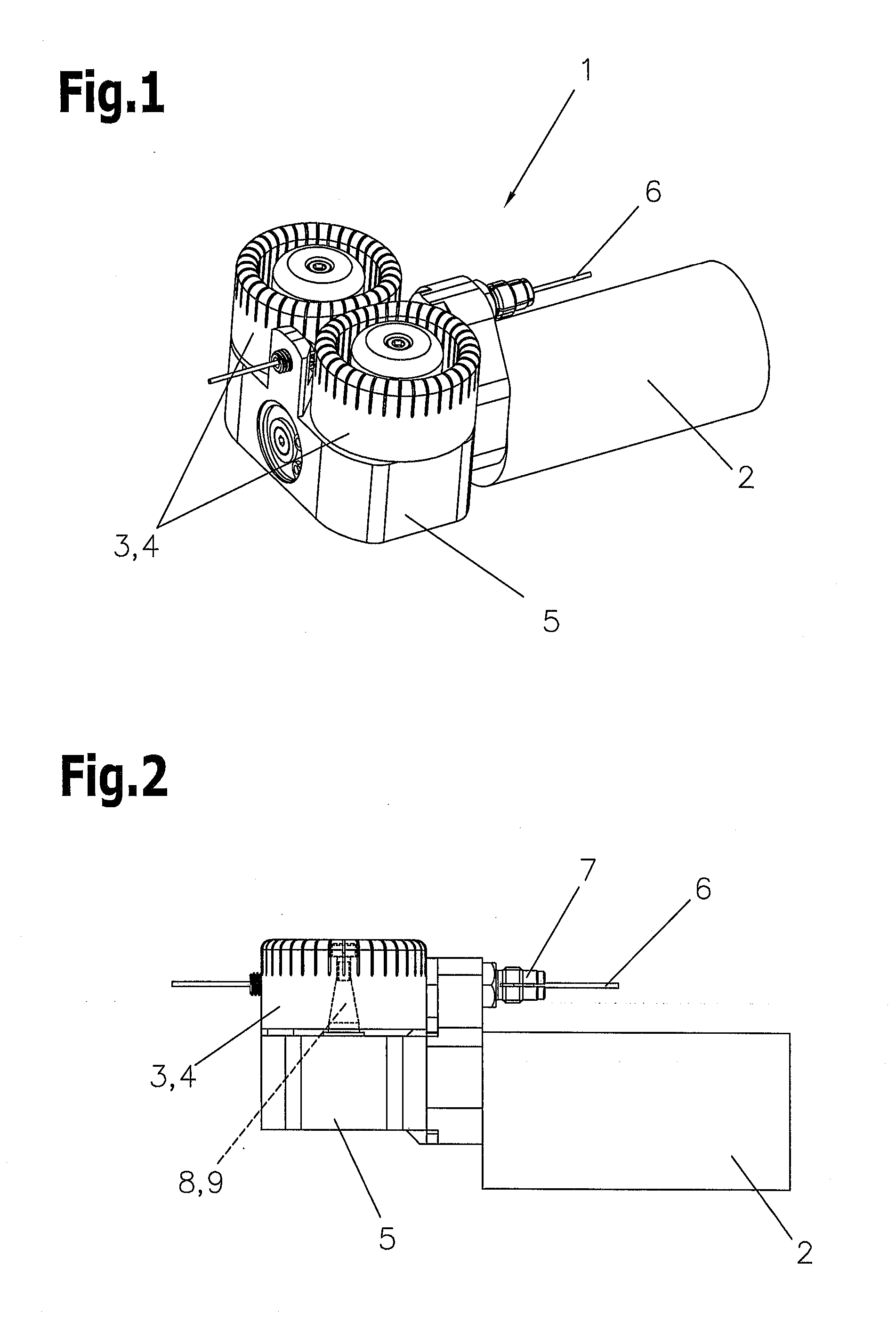
[0032]FIG. 1 illustrates a feeding device 1 with a drive motor 2 and a gear 5 connected thereto and an embodiment of the welding wire conveyor rollers 3, 4 in accordance with the invention for conveying the welding wire 6. By means of the welding wire conveyor rollers 3, 4 according to the invention complete clamping of the welding wire 6 to be conveyed is achieved. An adjustment means for adapting the feeding device 1 to the welding wire 6 is not required due to the elasticity of the welding wire conveyor rollers 3, 4 in accordance with the invention.

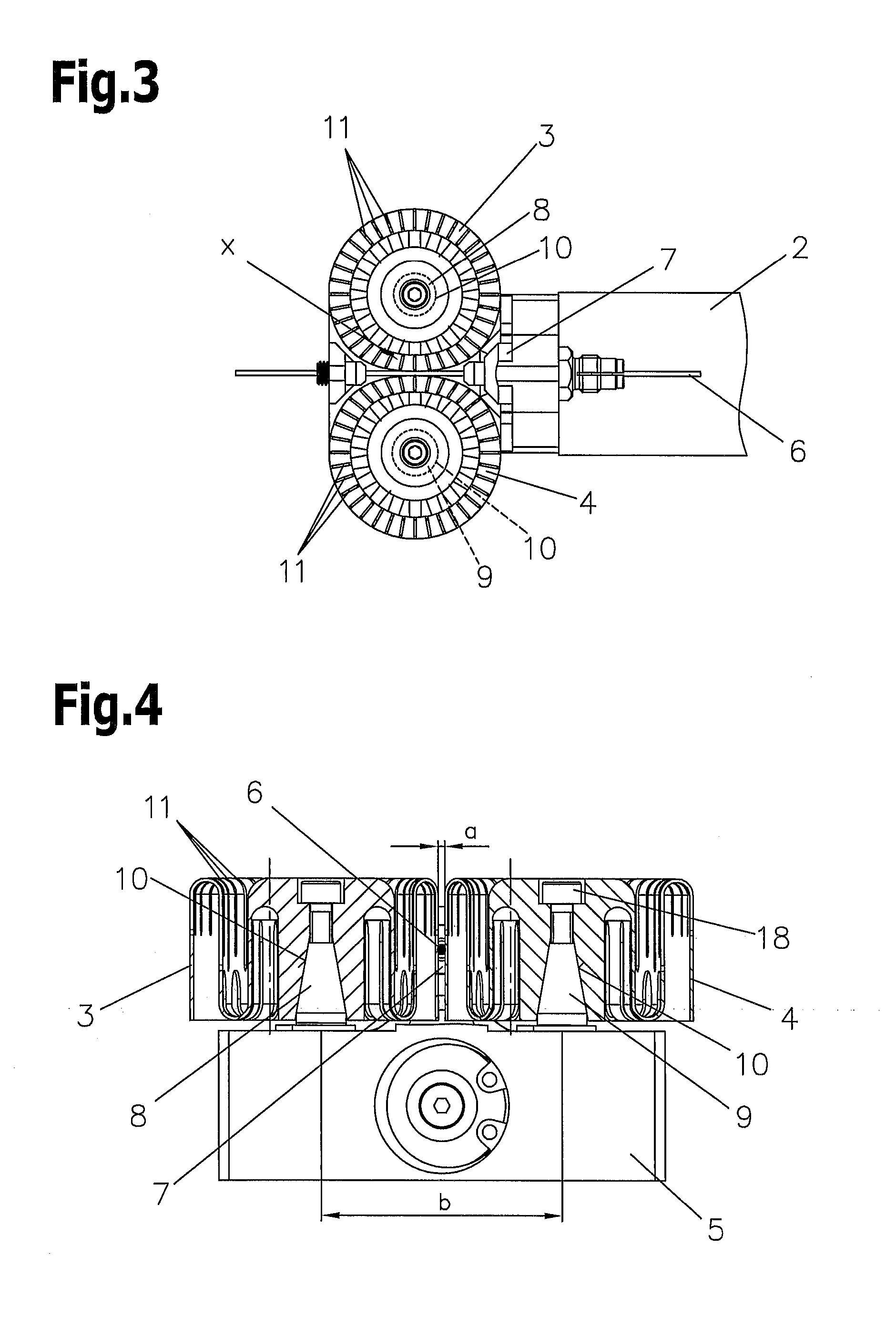
[0033]FIG. 2 illustrates the feeding device 1 of FIG. 1 in side view for a clearer illustration of the guiding of the welding wire 6 through the guiding sleeve 7 and the welding wire conveyor rollers 3, 4. The drive motor 2 drives the gear 5 which in turn rotates at least one of the receiving pins 8, 9 on which the welding wire conveyor rollers 3, 4 are mounted. The gear 5 is designed such that at least one of the receiving pins 8, 9 i...


PUM

PropertyMeasurementUnit
diameteraaaaaaaaaa
diameteraaaaaaaaaa
areaaaaaaaaaaa

Abstract

A welding wire conveyor roller for conveying a welding wire includes a receiving aperture for receiving a receiving pin, and a running surface for the welding wire, and a feeding device for conveying a welding wire includes a drive motor, at least two receiving pins arranged at a distance to each other, and at least two welding wire conveyor rollers with running surfaces for the welding wire which are placed upon the receiving pins by appropriate receiving apertures. For achieving improved conveying properties even with different welding wires, an area elastically deformable in the radial direction is arranged between the running surface and the receiving aperture of the welding wire conveyor rollers.

Description

CROSS REFERENCE TO RELATED APPLICATIONS[0001]Applicant claims priority under 35 U.S.C. §119 of Austrian Application No. A 50855 / 2013 filed Dec. 23, 2013, the disclosure of which is incorporated by reference.BACKGROUND OF THE INVENTION[0002]1. Field of the Invention[0003]The invention relates to a welding wire conveyor roller for conveying a welding wire, comprising a receiving aperture for receiving a receiving pin and a running surface for the welding wire, and to a feeding device for conveying a welding wire, comprising a drive motor, at least two receiving pins arranged at a distance to each other, and at least two welding wire conveyor rollers placed upon the receiving pins by appropriate receiving apertures and comprising running surfaces for the welding wire.[0004]2. Description of the Related Art[0005]Feeding devices for the conveying of welding wires comprise usually two conveyor rollers, one pressing roller and one counter roller between which the welding wire is clamped an...

Claims


Application Information

Patent Timeline
Patent Type & Authority Applications(United States)
IPC IPC(8): B23K9/133B23K9/12
CPCB23K9/1336B23K9/125
Inventor SPIESBERGER, ALFREDROLA, MAXIMILIAN
Owner FRONIUS INTERNATIONAL GMBH
Why Eureka
Try Eureka