One-way valve assembly

a one-way valve and assembly technology, applied in the direction of machines/engines, liquid fuel engines, positive displacement liquid engines, etc., can solve the problems of reduced force to be unbalanced during the operation of inflators, and complicated structure of conventional check valves, so as to improve the non-return effect of check valves, and eliminate the problem of unsmooth airflow and air leak

Inactive Publication Date: 2015-06-25
HUANG YING CHE +1
View PDF14 Cites 13 Cited by
  • Summary
  • Abstract
  • Description
  • Claims
  • Application Information

AI Technical Summary

Benefits of technology

[0016]According to an embodiment of the present invention, when the central member is a head member of an inflator or a suction device, a female thread can be disposed at the first inner compartment of the central member, and a corresponding male thread can be disposed at the plug member. After the male thread of the plug member is engaged with the female thread of the first inner compartment of the central member, the valve seat and the valve plate are restricted in the first inner compartment between the plug member and the first bottom portion of the central member. The valve plate is still able to move freely inside the second inner compartment.
[0017]With the simplified structure of the valve seat and the first inner compartment of the central member, the direction of airflow can be simply changed by reversing the direction of the valve seat inside the first inner compartment of the central member. In this way, a tubular body equipped with the one-way valve assembly of the present invention can achieve the functions of an inflator and a suction device simply by reversing the direction of the valve seat. In addition, the non-return effect provided by the present invention is also enhanced compared with the conventional check valves, and the problems of unsmooth airflow and air leakage are also eliminated. The components of the one-way valve assembly needed for use with an inflator and suction device are the same. In addition, there is no need to add new components or change the shape or structure of the components for different application as well. Hence, the one-way valve assembly is adapted to be used with any inflators or suction devices, including small portable inflator and large floor type of inflator. The assembling process of the one-way valve assembly according to the present invention is simple, and therefore the production cost can be lowered.

Problems solved by technology

However, the structure of such conventional check valve is rather complicated.
The check valve plate is not stable upon contact with the check valve seat, thereby causing the force to be unbalanced during the operation of the inflator.
As a result, the non-return effect of the check valve is reduced, and the air flow during the pumping process is not smooth as well.
In addition, due to the step-shaped design of the check valve seat and an end of the check valve seat being installed inside the air passage of the air pump rod, an end face at the front end of the check valve seat is not able to stay in close contact with the opposite surface, thereby causing air leakage.
Due to the design flaws in its structure, the usage of the conventional valve seat is limited.
The conventional valve seat can only be used in an inflator, and cannot be used in a suction device.
Hence, with the structure of the current valve seat, it is impossible to provide the function needed for an inflator and suction device in the same structure.

Method used


Image

  • One-way valve assembly
  • One-way valve assembly
  • One-way valve assembly

Examples


first embodiment

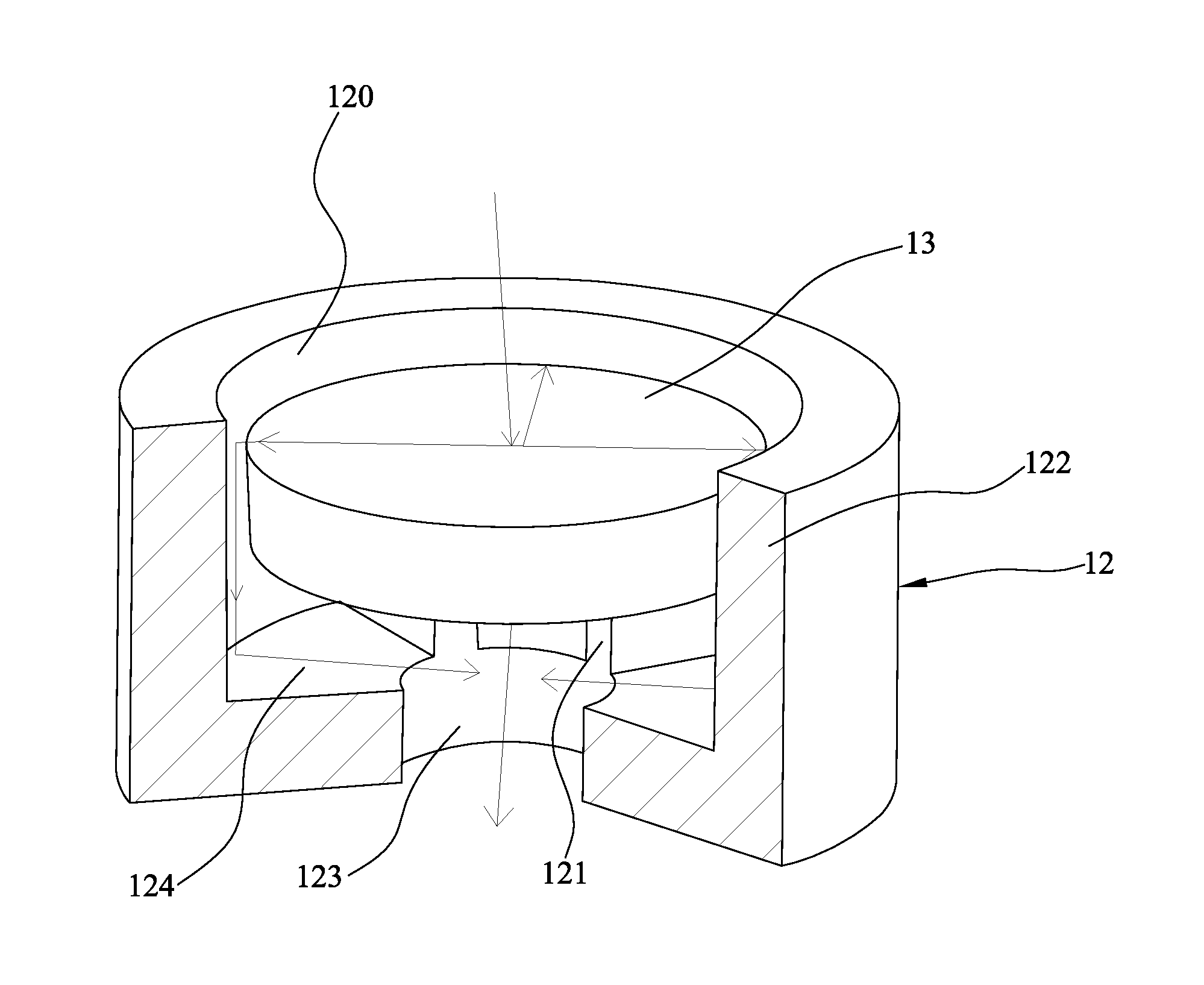
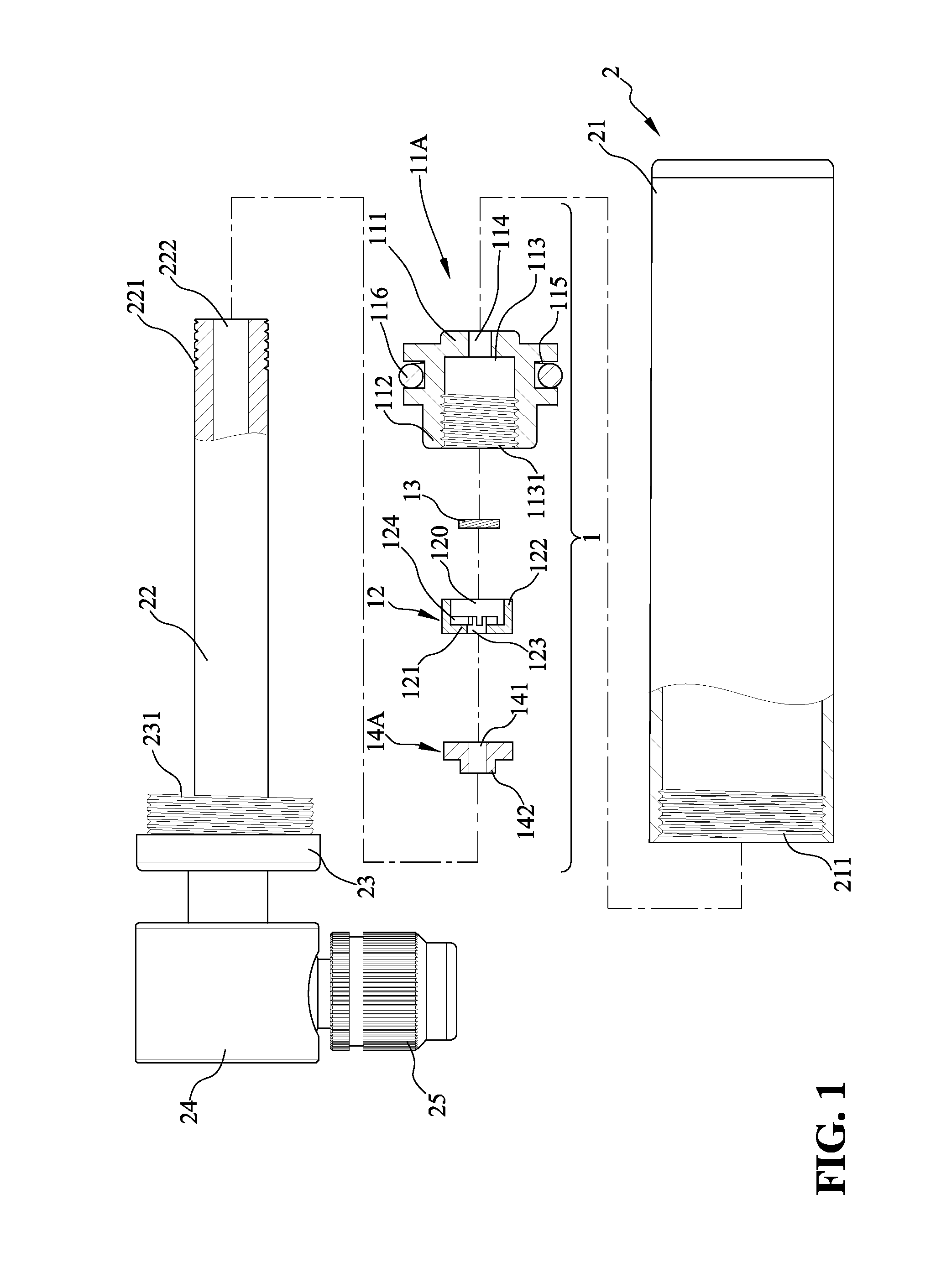
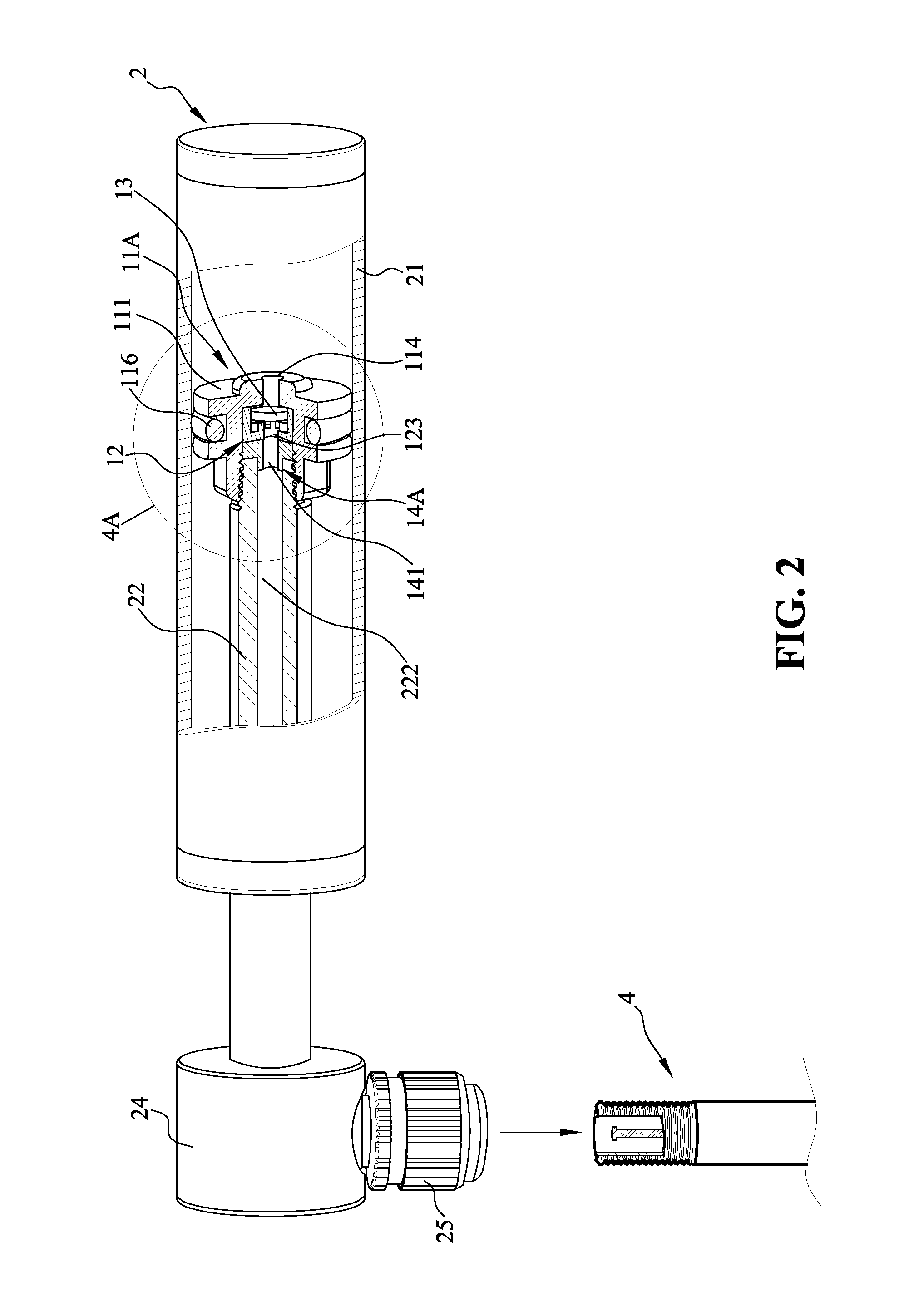
[0039]FIG. 1, FIG. 2, FIG. 4A and FIG. 4B are figures showing a first embodiment of the present invention, where the one-way valve assembly is adapted to be used in a small portable inflator 2. As shown in the figures, the one-way valve 1 includes a valve seat 12, a valve plate 13, a plug member 14A and a piston 11A. The piston 11A is used as a central member for receiving and assembling all the previous components. The inflator 2 includes a tubular body 21, a piston rod 22, a head member 24 for connecting the piston rod 22 and a cap 23, which is freely sleeved around the piston rod 22. A female thread 211 is disposed at the inner circumference of an end of the tubular body 21. The other end of the tubular body 21 is sealed. The piston rod 22 includes an air passage 222, which is axially in communication with the head member 24. The head member 24 further includes an air nozzle 25, which is in communication with the inner space of the head member. The air nozzle 25 can be connected ...

second embodiment

[0048]FIG. 5, FIG. 6, FIG. 7 A and FIG. 7B are figures showing a second embodiment of the present invention, where the one-way valve assembly is adapted to be used in a suction device 3. The structure of the one-way valve 1 according to the second embodiment is completely the same as the one-way valve 1 according to the first embodiment. The one-way valves 1 according to both embodiments both include a valve seat 12, a valve plate 13, a plug member 14A and a piston 11A. The piston 11A in the second embodiment is also used as a central member for receiving and assembling all the previous components. Hence, in order to avoid redundancies, the structure of the one-way valve 1 will not be explained again in the second embodiment. The structure of the suction device 3 is similar to the inflator 2 described in the first embodiment. The difference between the suction device 3 and the inflator 2 is that the air nozzle 25 in the inflator 2 is replaced with an air needle 35 at the head member...

third embodiment

[0053]FIG. 8, FIG. 9, FIG. 10A and FIG. 10B are figures showing a third embodiment of the present invention, where the one-way valve assembly is adapted to be used in another type of small portable inflator 2. As shown in the figures, the one-way valve 1 includes a valve seat 12, a valve plate 13, a plug member 14B and a head member 24, which also belongs to a part of the inflator 2. The inflator 2 includes a tubular body 21, a piston rod 22, a piston 11A for connecting the piston rod 22, and a head member 24 as mentioned above. A female thread 211 is disposed at an end of the tubular body 21 in the inner circumference thereof for engaging with the head member 24. The piston rod 22 passes through and extends beyond the other end of the tubular body 21, and a handle 223 is disposed at the part of piston rod 22 extending beyond the tubular body 21. In this way, when a user grabs the handle 223 to operate the piston rod 22 and create reciprocating motion in relevant to the tubular body...


PUM


Abstract

A one-way valve assembly is provided in the present invention, including a central member, a valve seat, a valve plate and a plug member. The central member includes a first inner compartment and a first through hole. The valve seat includes a second inner compartment and a second through hole. A plurality of recesses are formed on the bottom surface of the second inner compartment, so the second through hole is spaced apart from the bottom surface of the second inner compartment. The valve seat is seated inside the first inner compartment. The valve plate is seated inside the second inner compartment of the valve seat. The plug member includes a third through hole, and is seated inside the first inner compartment of the central member so the valve seat and the valve plate are restricted in the first inner compartment between the plug member and the central member.

Description

BACKGROUND OF THE INVENTION[0001]1. Field of the Invention[0002]The present invention relates to a valve assembly, more particularly, relates to a valve assembly that can be utilized in an air transmitting device such as an inflator or a suction device.[0003]2. The Prior Arts[0004]The one-way valve is a type of valve component commonly used in an inflator or a suction device. The purpose of the one-way valve is to prevent the back flow of the air after the air has passed through the valve. A typical inflator usually includes a tubular body, a head member disposed at the tubular body, an air nozzle connected to the head member, and a piston and a piston rod disposed inside the tubular body. The one-way valve is disposed at the piston or the head member. After the air nozzle is connected with the nozzle of the object to be inflated, one can operate the piston rod and the tubular body so the air inside the tubular body is compressed by the piston. The compressed air is then pushed thro...

Claims


Application Information

Patent Timeline
Patent Type & Authority Applications(United States)
IPC IPC(8): F16K15/02
CPCF16K15/02F04B33/005F16K15/023F04B53/127Y10T137/7904
Inventor HUANG, YING-CHEHUANG, CHUN-MING
Owner HUANG YING CHE
Why Eureka
Try Eureka