Systems for and methods of modeling, step-testing, and adaptively controlling in-situ building components

a technology for building components and systems, applied in the field of controllable building environments, can solve the problems of inefficiency, time-consuming and laborious, and difficult to model, and achieve the effects of reducing labor intensity, reducing labor intensity, and reducing labor intensity

Inactive Publication Date: 2015-06-25
NEXTRACKER LLC
View PDF12 Cites 86 Cited by
  • Summary
  • Abstract
  • Description
  • Claims
  • Application Information

AI Technical Summary

Benefits of technology

[0007]In accordance with the principles of the invention, performance models of HVAC systems and sub-systems are modeled more efficiently and accurately. (To simplify the discussion that follows, references to “HVAC components” include HVAC systems and sub-systems.) In one embodiment, HVAC performance models are generated using power readings from the building's power meter, rather than requiring separate meters for each component in the building. These models are derived independently of the spatial locations of the components, the types of components, and the methods for controlling the components, and are thus derived faster and with fewer resources. Once these models are generated, they can be used for different purposes, such as automatic testing, to ensure that the HVAC components are working properly; adaptively updating the models; and generating reports detailing cost savings based on adjustments to the environmental conditions.

Problems solved by technology

For a medium-sized office building this testing can take weeks; for a large office building, it can take months.
When the environmental and system performance data are eventually collected, the data can be used to model the HVAC units and their sub-components, though not efficiently.
Because prior art models must take all of these factors into account, the methods for generating them are time consuming, computationally difficult and intensive, and error-prone.
Furthermore, these models are static.
Once generated, they are not updated to reflect operating changes in HVAC components, such as due to age, damage, or current external weather or operating load.
Nor are they updated to reflect changes in building occupancy, such as when additional staff move into or are relocated within a building.

Method used


Image

  • Systems for and methods of modeling, step-testing, and adaptively controlling in-situ building components
  • Systems for and methods of modeling, step-testing, and adaptively controlling in-situ building components
  • Systems for and methods of modeling, step-testing, and adaptively controlling in-situ building components

Examples


Embodiment Construction

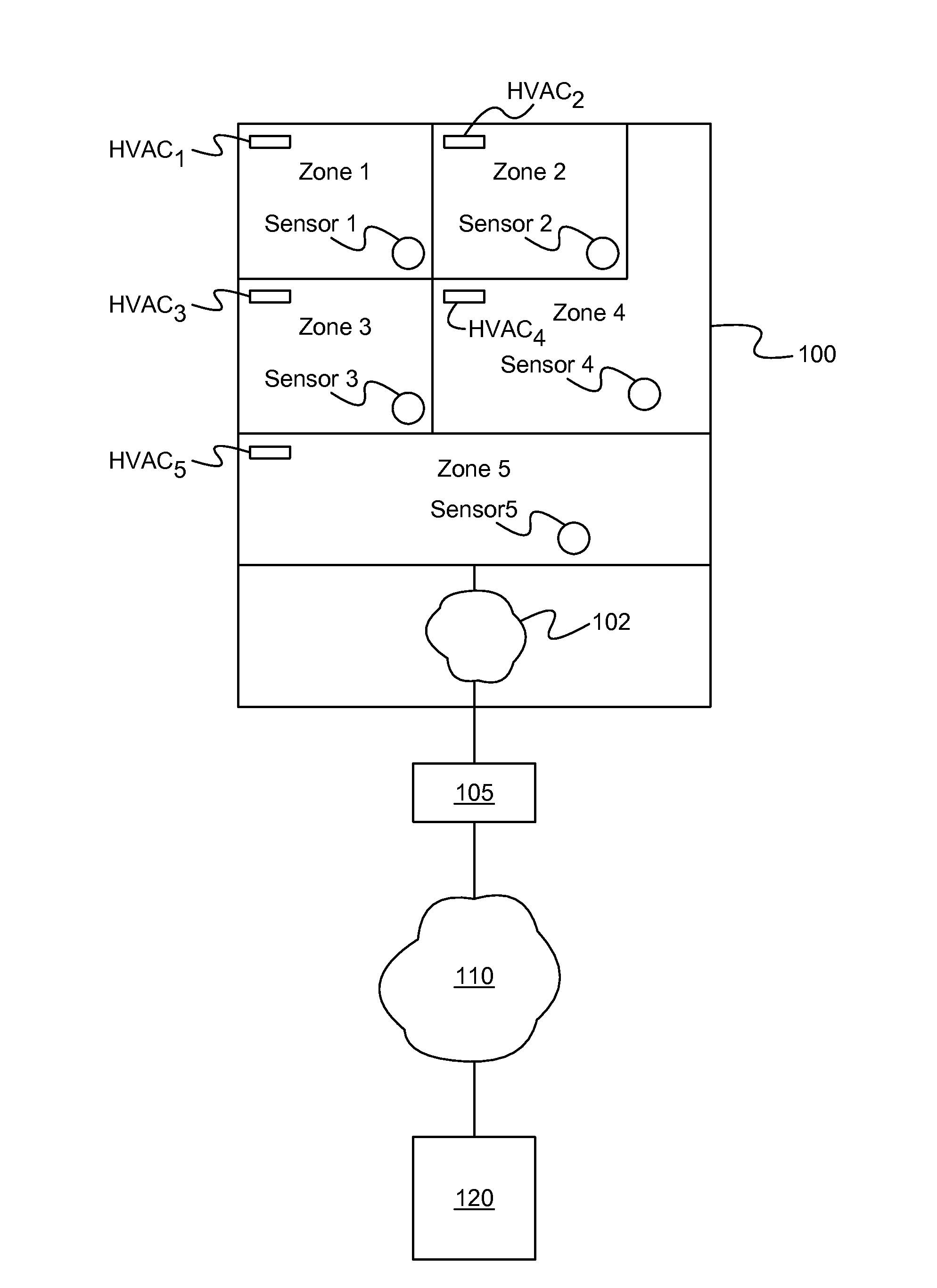
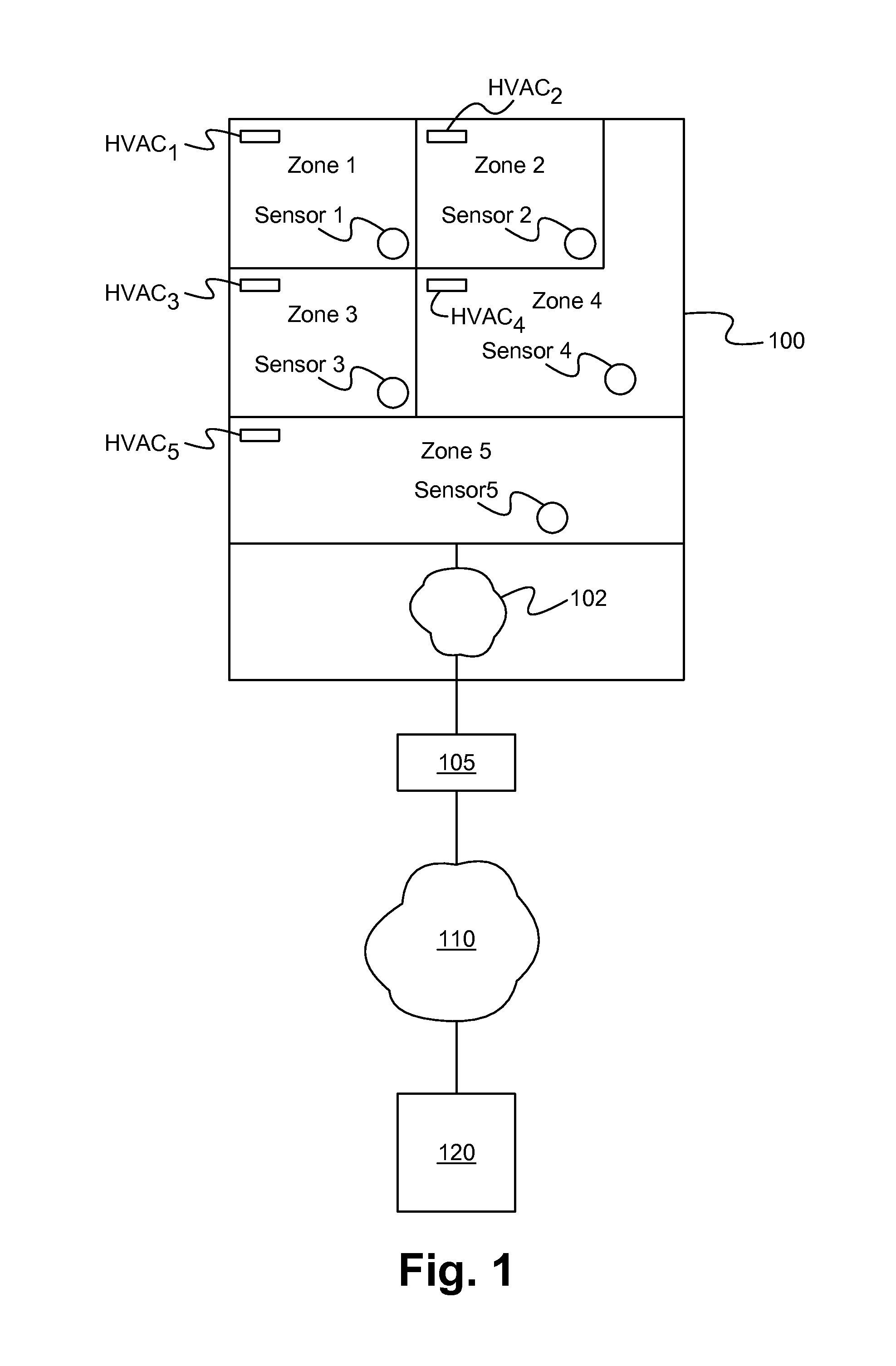
[0036]FIG. 1 shows a building 100 with multiple zones 1-5, each with its own thermal environment, and building automation system (also referred to as building management system “BMS”) 105, coupled over the Internet 110 to a control platform 120, used to model performance in the thermal environments, according to one embodiment of the invention. Each of the zones 1-5 has one or more heating, ventilation, and air-conditioning (HVAC1-5) components for controlling the temperature, humidity, air flow, air flow rate, rate, or other environmental state within the corresponding zone 1-5, and a corresponding sensor 1-5 for measuring the environmental state in that zone. As discussed in more detail below, the modeling for each HVACi component (i=1 to 5) is performed using a power consumption reading for a group of zones in the entire building 100, rather than a power reading taken for each HVACi component. Advantageously, this modeling process does not require a power consumption meter for ea...


PUM


Abstract

A system for and method of modeling thermal performance characteristics of HVAC components in a building uses the building power or other meter to measure power consumed by the components. The models are used to test the components, preferably during off hours, to ensure proper and efficient operation. Preferably, the testing software is written in a high-level interpretive language that is independent of the HVAC component being modeled. The models are adaptively maintained by periodically ensuring that their measured output matches the predicted output. When the two do not match, the model parameters are updated. These models can also be used to generate reports comparing costs and cost savings for different temperature and other environmental settings within selected zones in the building.

Description

RELATED APPLICATIONS[0001]This application claims priority under 35 U.S.C. §119(e) of the co-pending U.S. provisional patent application Ser. No. 61 / 919,547, filed Dec. 20, 2013, and titled “System, Method and Platform for Characterizing In-Situ Building and System Component and Sub-component Performance by Using Generic Performance Data, Utility-Meter Data, and Automatic Step Testing,” and the co-pending U.S. provisional patent application Ser. No. 62 / 022,126, filed Jul. 8, 2014, and titled “System, Method and Platform for Automated Commissioning in Commercial Buildings,” both of which are hereby incorporated by reference in their entireties.FIELD OF THE INVENTION[0002]This invention relates to controlled building environments. More particularly, this invention relates to modeling, monitoring, commissioning, and adjusting heating, ventilation, and air conditioning systems and components in buildings.BACKGROUND OF THE INVENTION[0003]Environments within office and other buildings are...

Claims


Application Information

Patent Timeline
Patent Type & Authority Applications(United States)
IPC IPC(8): G06F17/50G05B15/02F24F11/00
CPCG06F17/5009G05B15/02F24F11/006G06F30/13G06F30/20G06F2119/06G06F2119/08
Inventor BORRELLI, FRANCESCODALY, ALLANMA, YUDONGWOOTTON, BRUCE C.
Owner NEXTRACKER LLC
Why Eureka
Try Eureka