Dental syringe tip devices, systems and methods

a technology which is applied in the field of dental systems, methods and devices for dental syringes, can solve the problems of limited use of dental syringes, the amount of water being ejected from the pressurized air port, and the leakage of water into the designated pressurized air port of dental syringes and tips, so as to reduce the likelihood of fluid leakage, reduce the possibility of leakage, or the effect of elimination

Inactive Publication Date: 2015-07-02
BERKELY DONOVAN
View PDF2 Cites 5 Cited by
  • Summary
  • Abstract
  • Description
  • Claims
  • Application Information

AI Technical Summary

Benefits of technology

[0005]Another aspect of the dental systems, methods and devices described herein is the recognition of a need to reduce the likelihood of fluid leakage from one passage to a second passage. For example, some dental syringes and tips can leak water into the designated pressurized air port. This can result in some amount of water being ejected from the pressurized air port when the operator intended that only pressurized air be released. As should be apparent, this can pose potentially significant issues when leaked fluid is ejected from an improper port. As such, one feature of the dental systems, methods and devices described herein is a reduction, or potential elimination, of leakage from one fluid channel to another fluid channel.

Problems solved by technology

Dental syringes are often limited to a fixed level of fluid pressure such as a fixed water output pressure from the water port and fixed air pressure output from the pressurized air port.
For example, some dental syringes and tips can leak water into the designated pressurized air port.
This can result in some amount of water being ejected from the pressurized air port when the operator intended that only pressurized air be released.
As should be apparent, this can pose potentially significant issues when leaked fluid is ejected from an improper port.

Method used


Image

  • Dental syringe tip devices, systems and methods
  • Dental syringe tip devices, systems and methods
  • Dental syringe tip devices, systems and methods

Examples


Embodiment Construction

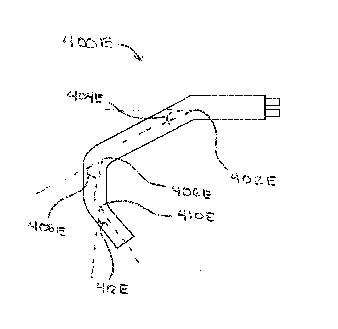
[0199]As will be described, the present application relates to a syringe tip devices and system and methods for producing such a syringe tip device and system. It should be appreciated that while the figures and description herein often refers to syringe tips, which can be used on a dental syringe, in modified embodiments the syringe tips can be applied to other types of fluid flow devices in which a syringe tip can be used to direct the fluid flow from the fluid flow device. It should be appreciated that, for purposes of this disclosure, “fluid” includes gases, liquids, and solids capable of being transported via gas or liquid transport, such as solid powders and the like.

Dental Syringe System

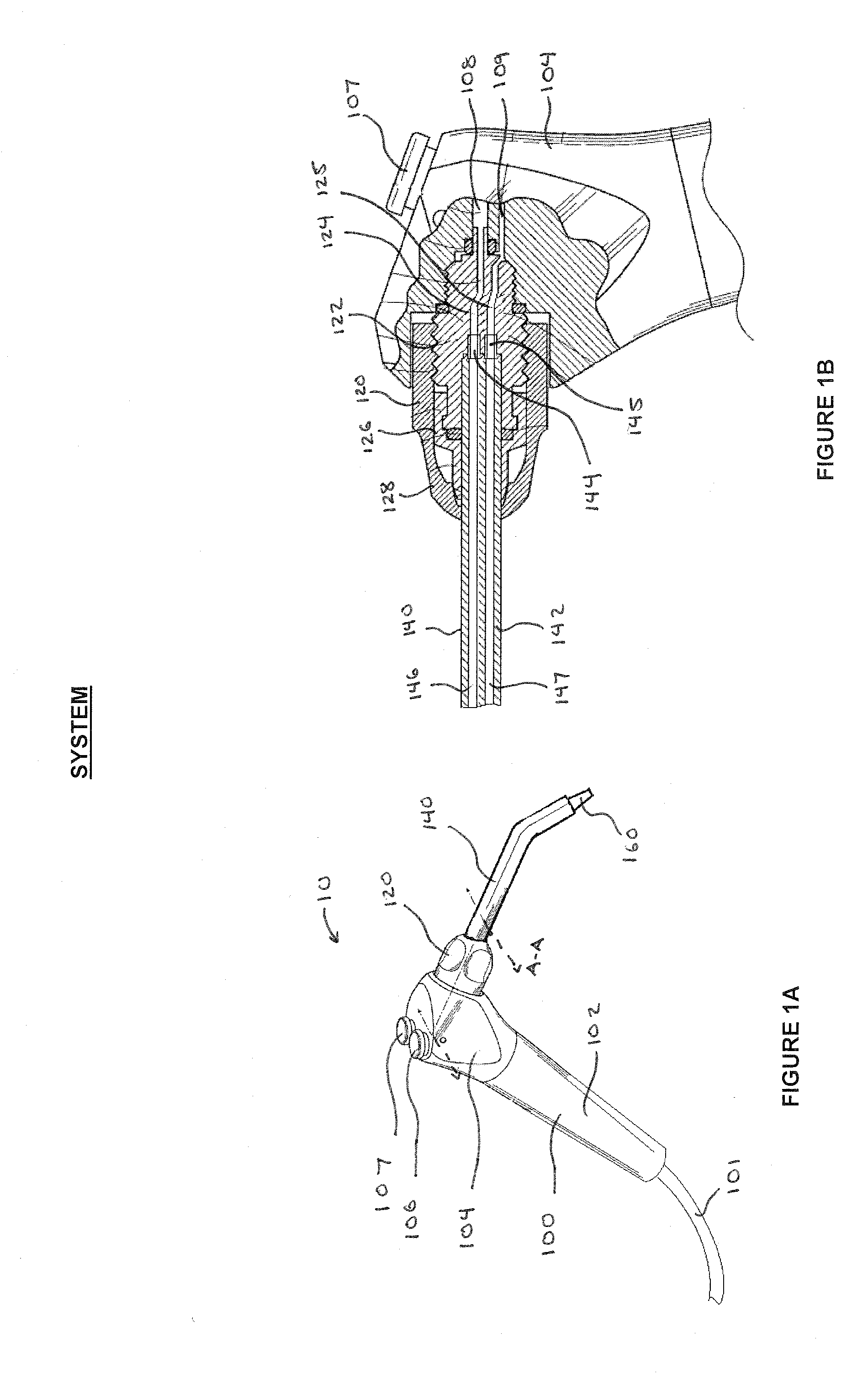
[0200]FIGS. 1A and 1B illustrate a general dental syringe system 10 which can include a dental syringe 100, a syringe tip adaptor 120, a syringe tip 140, and a tip modifier 160. The dental syringe 100 can be a handheld device which includes a conduit 101 for connecting the dental syringe 100 t...


PUM

PropertyMeasurementUnit
acute angleaaaaaaaaaa
angleaaaaaaaaaa
anglesaaaaaaaaaa

Abstract

A dental syringe tip system for attachment to a dental syringe. The dental syringe tip system can include components such as an outer core, an inner core, and a carrier which can be combined in a multitude of combinations to achieve different fluid flow characteristics, such as discharge pressure and discharge pattern, through the dental syringe tip. The outer core and inner core can have passages designed to modify fluid flow characteristics. In addition, the outer core and inner core can have additional connectors for receiving fluids from sources other than a dental syringe. Some or all of the components can be separate to be assembled by a manufacturer or an end-user. Assembly of multiple components can be facilitated by retention features located on the components.

Description

REFERENCE TO RELATED APPLICATION[0001]This application claims priority from U.S. Provisional Patent Application Ser. No. 61 / 895,658, filed Oct. 25, 2013, the entire content of which is incorporated herein by reference.FIELD OF THE INVENTION[0002]The present invention relates to dental systems, methods and devices for dental syringes.BACKGROUND OF THE INVENTION[0003]The dental syringe is a multi-purpose dental apparatus which is often used by dentists, dental assistants, dental hygienists, and other such personnel for a wide-range of dental visits. The dental syringe often includes both a water port and a pressurized air port and can be used for providing irrigation to a target site, clearing or removing debris from a target site, drying a target site for bonding with another dental apparatus, and a variety of other uses. Generally, such dental syringes include a syringe tip which directs the flow of water and air from the dental syringe to the target site. Due to the proximity of th...

Claims


Application Information

Patent Timeline
Patent Type & Authority Applications(United States)
IPC IPC(8): A61C17/02
CPCA61C17/0217A61M5/3286A61M5/329A61M5/3298Y10T29/49567
Inventor BERKELY, DONOVAN
Owner BERKELY DONOVAN
Why Eureka
Try Eureka