Loading Mechanism

Inactive Publication Date: 2015-07-02
BALEX MARINE DEV LTD
View PDF1 Cites 7 Cited by
  • Summary
  • Abstract
  • Description
  • Claims
  • Application Information

AI Technical Summary

Benefits of technology

This patent describes a device that can automatically load and unload a boat, and adjust the position of its rollers as it moves out of the water. This allows for easier handling of larger boats and ensures they stay upright while on the water.

Problems solved by technology

However, significant strength is required to move a heavy boat over rollers.
This means that many boat users may struggle to push a boat so as to load and unload it from a trailer.
However, these can be fiddly to use.
This can be difficult to achieve.
In addition, a boat user often gets wet which many people wish to avoid.
Furthermore, manual winches still require strength or effort to load the boat.
Again, not all boat users possess sufficient strength to load the boat.
A further problem of many boat trailers is that these must be submerged in water in order for a boat to be loaded onto the trailer.
Exposure of the trailer to water, and in particular salt water, can accelerate the rate of rusting of the trailer and its components.
This often can be logistically difficult to achieve.
A further issue with the boat trailer disclosed by PCT Application No. 2004 / 000667 is that the chain drive mechanism has exposed moving parts such as the drive chain.
Those parts may be susceptible to rusting, which can be accelerated due to exposure to salt water or other damage.
That chain drive mechanism may also pose a safety risk due to the exposed / moving parts.
Yet a further problem of the boat trailer disclosed in this patent is that the rollers struggle to transfer sufficient force to the boat to efficiently move that onto and off from a trailer.
However, this type of boat trailer cannot easily be used with launching boats on inclined launching areas such as boat ramps.
As discussed above, such submersion can lead to wear and tear or rusting of the components.

Method used


Image

  • Loading Mechanism
  • Loading Mechanism
  • Loading Mechanism

Examples


Embodiment Construction

[0112]Aspects of the present invention have been described by way of example only and it should be appreciated that modifications and additions may be made thereto without departing from the scope thereof.

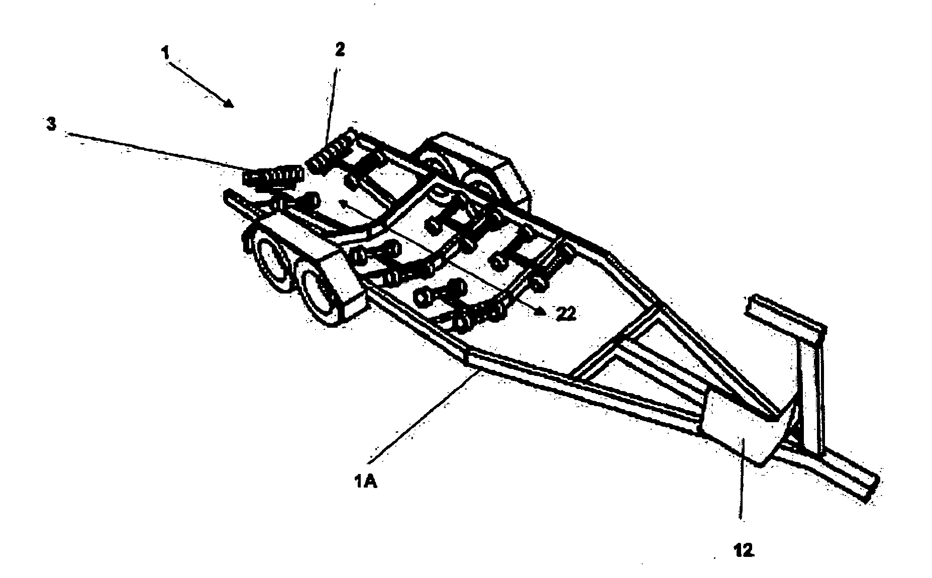
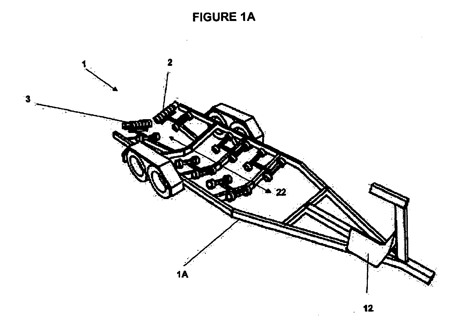
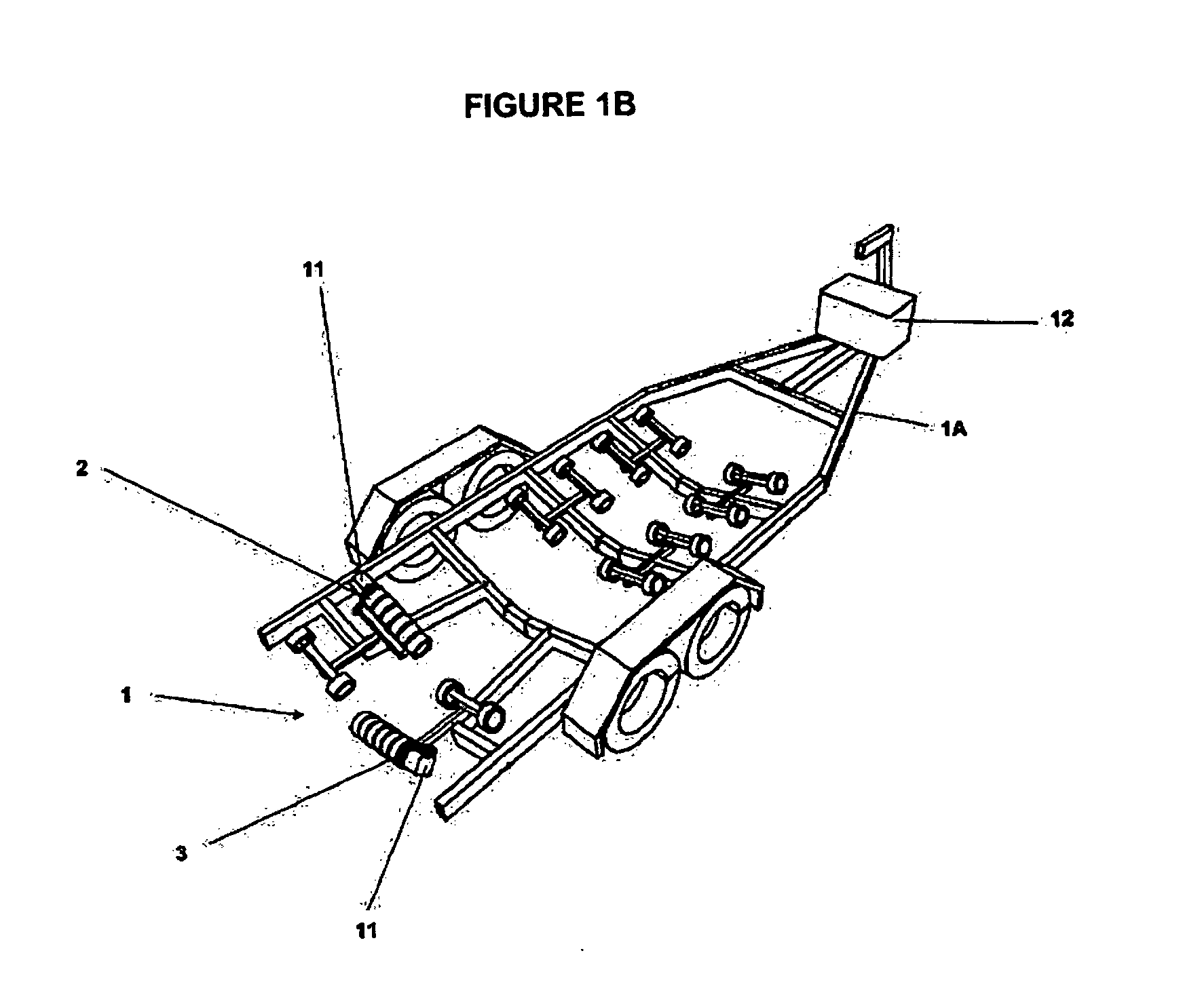
[0113]There is provided a loading mechanism generally indicated as (1). The loading mechanism (1) is secured to a boat trailer (1A).

[0114]The loading mechanism (1) may be sold as a kitset of parts including instructions on how to assemble the loading mechanism (1) to the boat trailer (1A). The instructions (not shown in the Figures) can include any or all of the steps discussed herein.

[0115]Referring first to FIGS. 1A, 1B, and FIGS. 2A, 2B.

[0116]However, the roller assemblies (2, 3) can pivot with respect to each other so as to change their orientation with respect to each other. In the embodiment shown in the Figures, the roller assemblies (2, 3) can pivot such that they are substantially parallel, with their axis (Y) aligned. This is important to roller assemblies (2, 3) transfer...


PUM


Abstract

This invention relates to a loading mechanism, including a first roller assembly and second roller assembly, at least one mounting for the first and second roller assemblies, wherein the first roller assembly and second roller assembly each have a longitudinal axis, a drive mechanism configured to rotate the first roller assembly and second roller assembly, so as to move an object, wherein as the weight of the object applies pressure to at least one of the first and second roller assemblies the mounting allows the roller assemblies to move so as to change the angle between the longitudinal axis of the first and second roller assemblies.

Description

TECHNICAL FIELD[0001]The present invention relates to a loading mechanism.BACKGROUND ART[0002]Trailers are used to store and transport boats.[0003]The loading and unloading of a boat onto the trailer is facilitated by rollers mounted on the trailer. The boat is moved over the rollers to move it onto or off from (load / unload) the trailer.[0004]The simplest mechanical way to load or unload a boat is to push it. However, significant strength is required to move a heavy boat over rollers. This means that many boat users may struggle to push a boat so as to load and unload it from a trailer.[0005]Winches are often used to drag boats out of the water, over rollers, and thereby onto the trailer. However, these can be fiddly to use. It is necessary to align the boat with the trailer and secure the winch rope to the front of the boat. This can be difficult to achieve. In addition, a boat user often gets wet which many people wish to avoid.[0006]Furthermore, manual winches still require stren...

Claims


Application Information

Patent Timeline
IPC IPC(8): B60P3/10B60P1/52
CPCB60P1/52B60P3/1066B63C3/12
Inventor BACON, LEX NOEL
Owner BALEX MARINE DEV LTD
Why Eureka
Try Eureka