
Rotary valve seal member and rotary valve using same

a technology of rotary valve and seal member, which is applied in the direction of engine seals, plug valves, valve arrangements, etc., can solve the problems of increasing the number of parts and assembly steps, increasing the overall size of the valve, and unavoidably complicating assembly, so as to increase the dimensional tolerance of the compression wall, increase the sliding resistance, and reliably prevent twisting and drooping

Inactive Publication Date: 2015-07-02
NIPPON THERMOSTAT CO LTD
View PDF6 Cites 14 Cited by
  • Summary
  • Abstract
  • Description
  • Claims
  • Application Information

AI Technical Summary

Benefits of technology

The present invention is a rotary valve seal member that is used in a valve housing to seal the space between the outer surface of the valve element and the inner wall of the valve housing. The seal member is made of an elastic material and has a three-dimensional structure consisting of an oval portion and a rectangular portion. The oval portion is designed to seal the space between the valve element and the inner wall of the valve housing, while the rectangular portion is retained within an annular groove in the valve housing to hold the seal member in place. The seal member is positioned in the valve housing to ensure a secure seal with the valve element and prevent twisting and drooping of the seal member during compression. The technical effects of this invention include improved sealing efficiency, reduced sliding resistance, and increased tolerances of the compression wall.

Problems solved by technology

More specifically, with the ordinary O-ring used as a seal member, when inserted between the valve element and the valve housing, the O-ring, which contacts the outer surface of the valve element, gets wrenched and twisted by the rotation of the valve element, requiring provision of a reinforcing member on the inside and the outside of the O-ring, thereby increasing the number of parts and assembly steps, unavoidably complicating assembly, and requiring that the space between the reinforcing member and the O-ring be made small to prevent the O-ring from getting caught therein.
However, if the O-ring is made thick, everything else becomes bigger as well, from the dimensions of the O-ring in the direction of compression (groove depth) to the inner and outer diameters of the O-ring (groove width), leading not only to an overall increase in the size of the valve but also to an increase in sliding resistance since the area of the outer surface of the valve element that the seal member contacts as the valve element slides increases, risking problems such as hindering movement of the valve element and wearing out the O-ring.

Method used


Image

  • Rotary valve seal member and rotary valve using same
  • Rotary valve seal member and rotary valve using same
  • Rotary valve seal member and rotary valve using same

Examples


Embodiment Construction

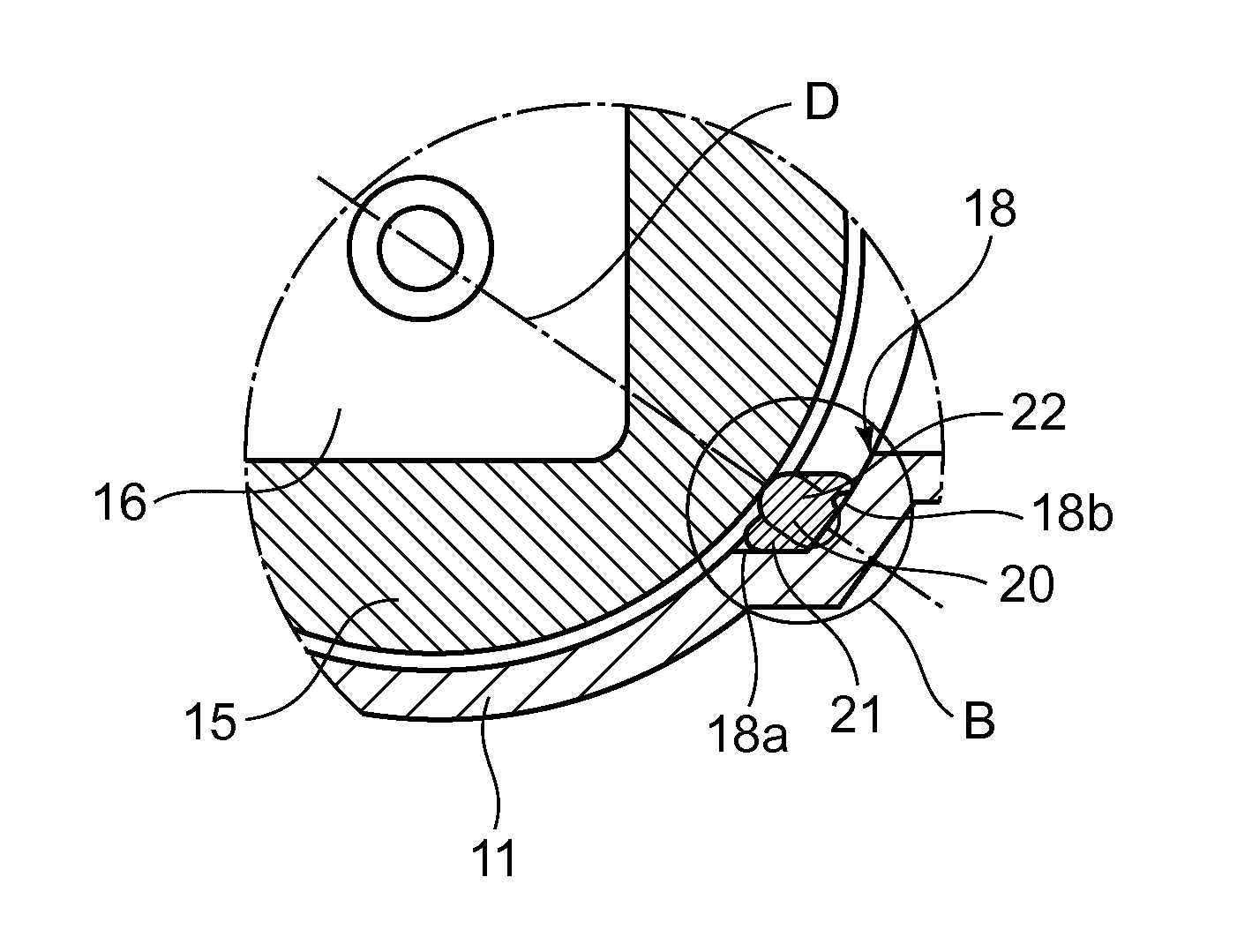
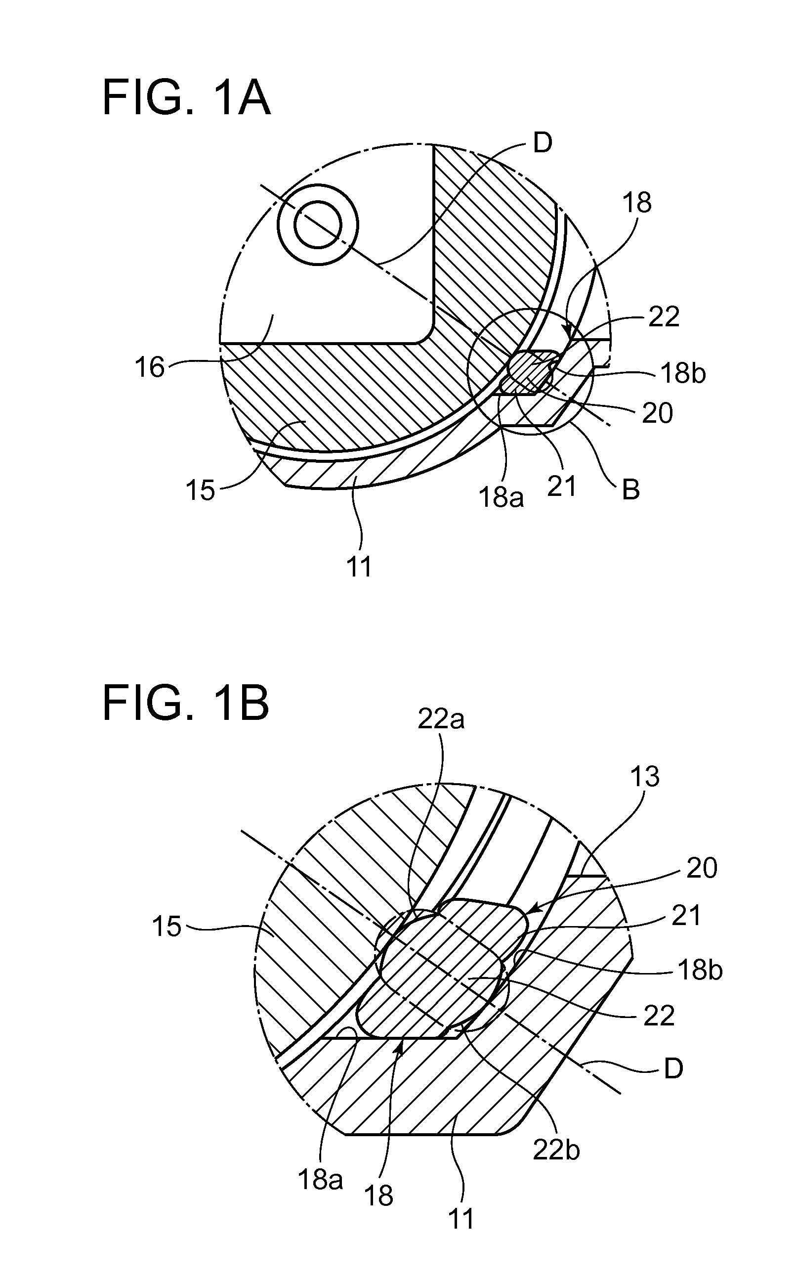
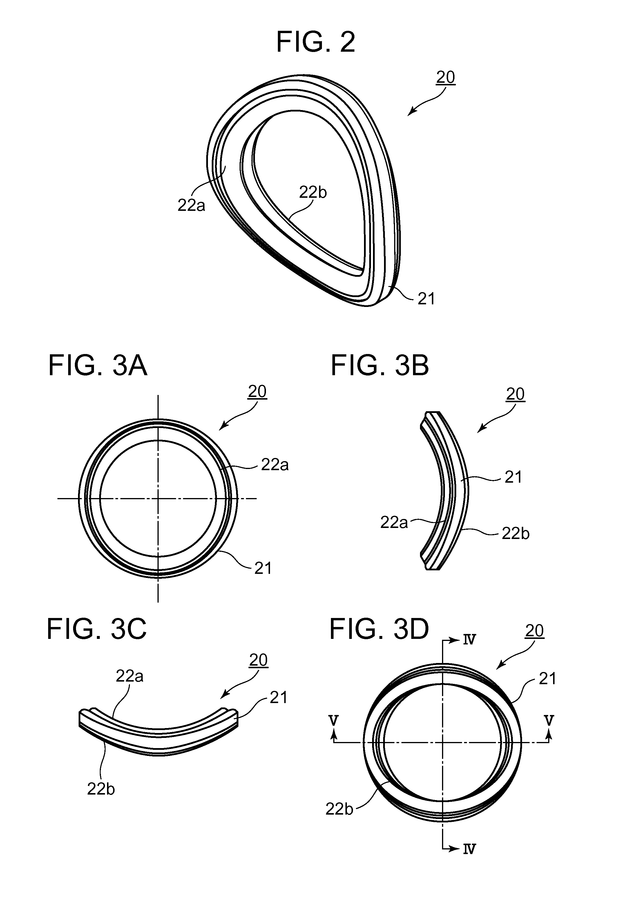
[0044]An annular seal member that seals a portion in contact with the outer surface of a valve element that rotates, turns, or slides is formed as a ring having in cross-section an oval portion that is aligned with the normal line to the outer surface of the valve element, with a bulge at the end of the seal member protruded and pressed against the valve element outer surface, and a rectangular portion, embedding the oval portion in a state in which the oval portion is aligned with the normal line to the outer surface of the valve element, with the outside of the rectangular portion in contact with and retained by the wall of an annular groove inside the valve housing.

[0045]FIGS. 1 through 5 show a rotary valve seal member according to the present invention and an embodiment of a rotary valve using the seal member. The present embodiment is described using as an example a case in which the seal member is adapted to a rotary valve used as a flow control valve in an appropriate fluid ...


PUM


Abstract

A rotary valve seal member that is held in sliding contact with a valve element that rotates, turns, or slides within a valve housing of a rotary valve and is capable of providing a secure seal as the valve element operates. The seal member has the structure of a three-dimensional ring having a cross-section composed of an oval portion, aligned with a normal line to the outside of the valve element and having a bulge at the end that protrudes and presses against the outer surface of the valve element, and a rectangular portion, into which the oval portion is integrated in a state in which the oval portion is aligned with the normal line to the outside of the valve element, that is retained within an annular groove with the outer side of the rectangular portion in contact with the wall of the annular groove.

Description

TECHNICAL FIELD[0001]The present invention relates to a rotary valve seal member for sealing a cylindrical or spherical valve element that rotates, turns, or slides, from flow control valves used in automobile cooling systems and the like to rotary valves such as ball valves used in water faucets and other plumbing fixtures, and to a rotary valve using the same.BACKGROUND ART[0002]In rotary-type flow rate control valves used in automobile cooling systems, for example, a container arrangement in which a substantially cylindrical valve element inside a valve housing can be rotated is known (see, for example, Patent Document 1).[0003]Briefly, in this rotary-type flow rate control valve, together with using a cylindrical valve element, an annular seal ring is inserted into an annular groove formed in the rim of an opening of a passage provided continuous with a valve chamber inside the valve housing to prevent fluid leakage and to provide the desired operation by moving the valve elemen...

Claims


Application Information

Patent Timeline
Patent Type & Authority Applications(United States)
IPC IPC(8): F16K5/06
CPCF16K5/0689F16J15/062F16J15/106F16K5/0464F16K5/0668
Inventor KUSAKABE, FUMITO
Owner NIPPON THERMOSTAT CO LTD
Learn More