
Smart voltage reduction and reverse power operating mode determination for load tap charging transformers and voltage regulators

Active Publication Date: 2015-07-02
BECKWITH ELECTRIC
View PDF2 Cites 2 Cited by
  • Summary
  • Abstract
  • Description
  • Claims
  • Application Information

AI Technical Summary

Benefits of technology

The present disclosure aims to provide better means to reduce voltage in a power distribution system and to effectively respond to varying demands in an electric power generation, transmission, and distribution system.

Problems solved by technology

However, some system emergencies results in an interruption of normal electric power generation.
When this occurs the system generation is not able to meet the load demand due to loss of a major generator.
Other times unusually high load demand occurs due to extreme weather.
Traditional voltage reduction schemes never provided the amount of requested voltage reduction by reducing the bandcenter due to the use of bandwidth.

Method used


Image

  • Smart voltage reduction and reverse power operating mode determination for load tap charging transformers and voltage regulators
  • Smart voltage reduction and reverse power operating mode determination for load tap charging transformers and voltage regulators
  • Smart voltage reduction and reverse power operating mode determination for load tap charging transformers and voltage regulators

Examples


Embodiment Construction

[0020]The present disclosure relates to a system for using load tap changing (LTC) transformers and voltage regulators (VR) to more accurately reduce the voltage in a power transmission and distribution system. It further relates to a system for determining the operating mode for LTC transformers and VRs. Corresponding methods are also disclosed. The various components of the present system, and the manner in which they interrelate, are more fully described hereinafter.

Smart Voltage Reduction

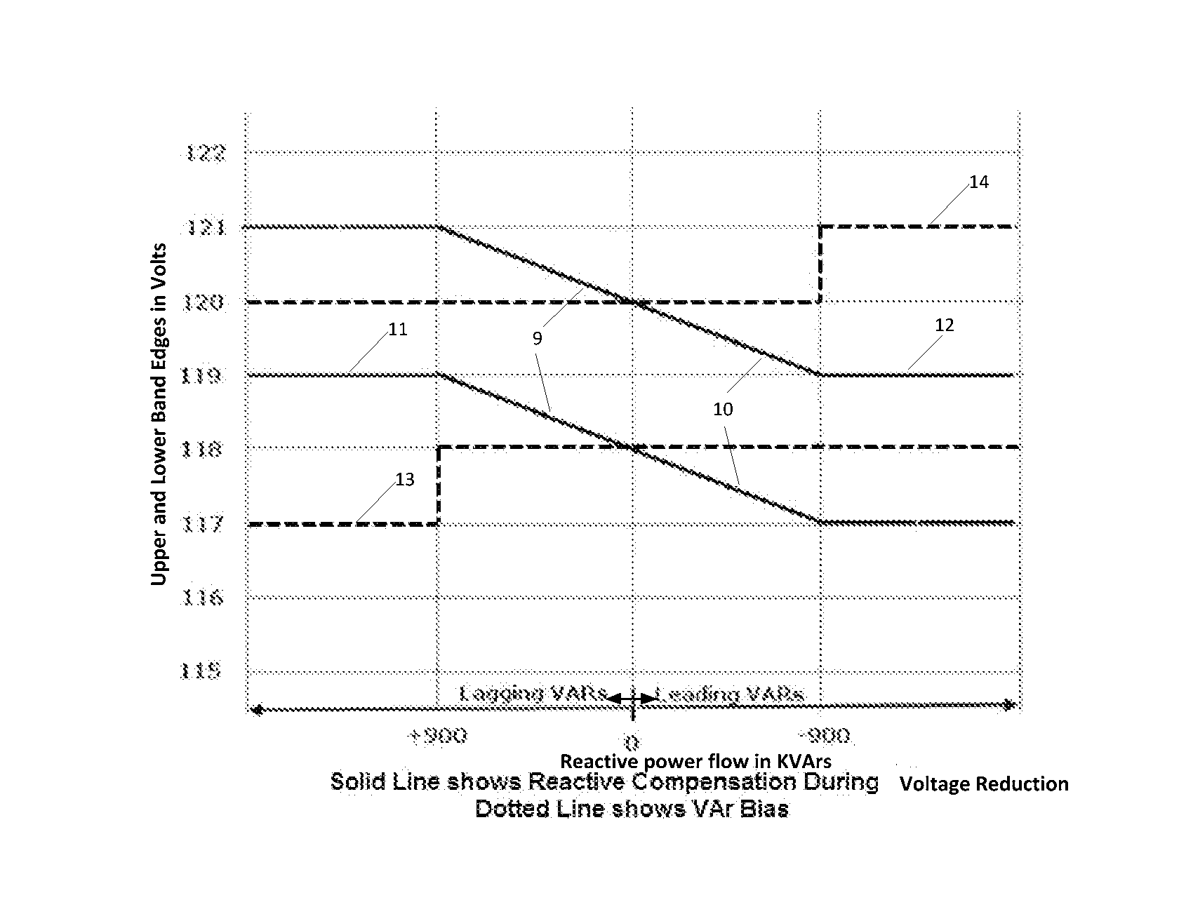
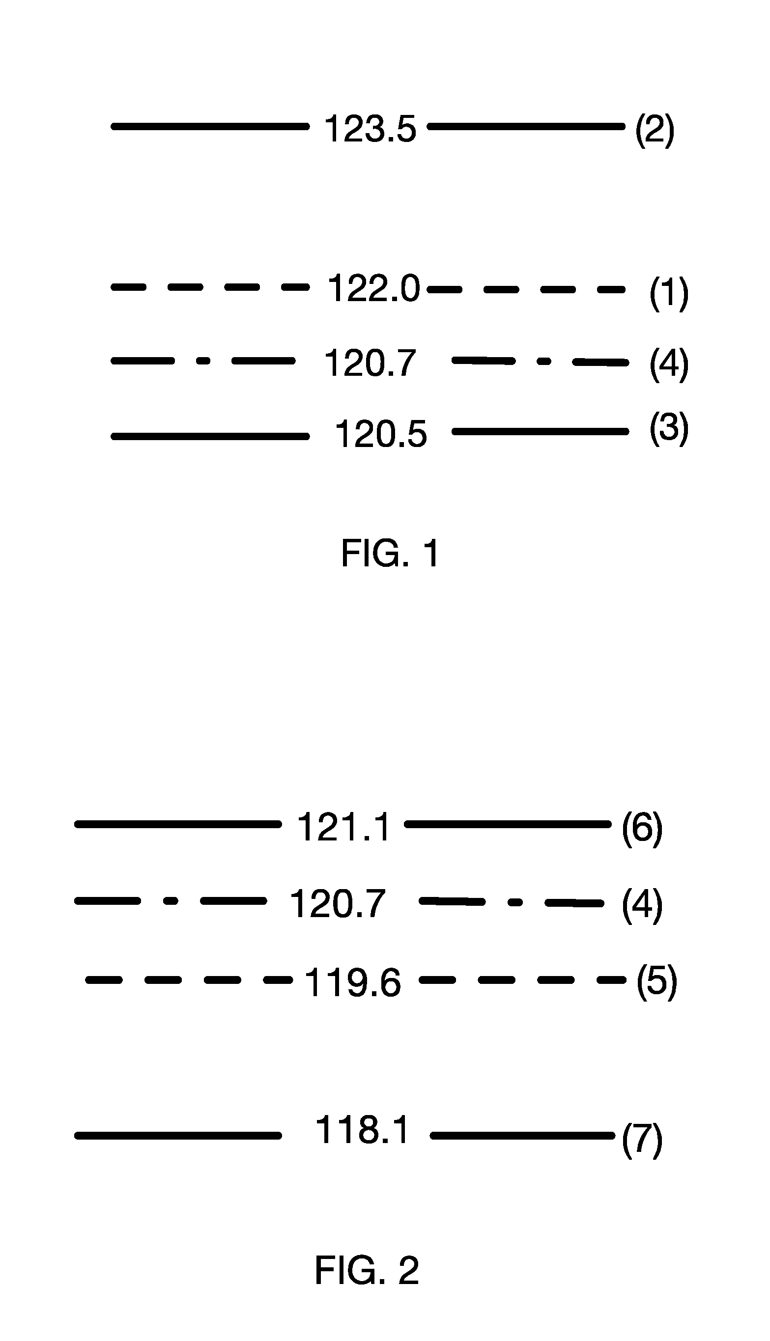
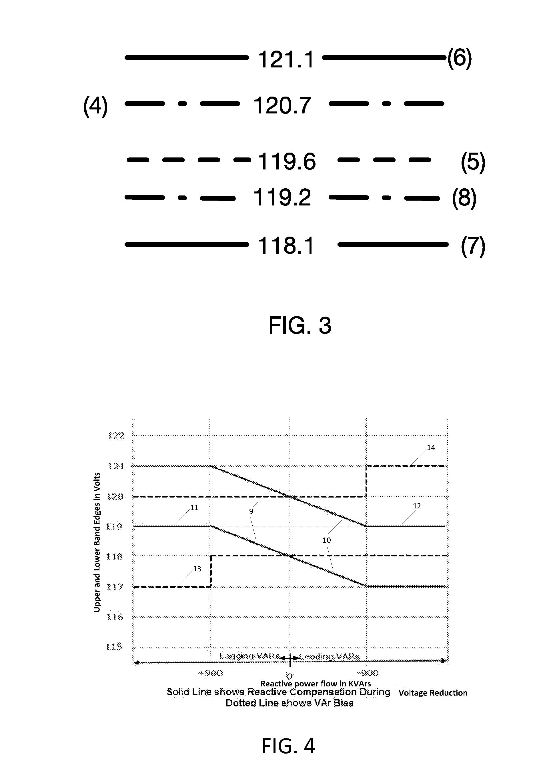
[0021]FIG. 1 is a graph depicting an example of the control settings of a tapchanger. Reference 1 is the bandcenter at 122 volts; reference 2 is the upper band edge at 123.5 volts; reference 3 is the lower band edge at 120.5 volts. The measured voltage is referenced by 4 at 120.7 volts. The difference in voltage between the upper band edge at 2 (123.5 V) and the lower band edge at 3 (120.5 V) is called the bandwidth setting. In this example the bandwidth setting is 3 volts. In this example, a ta...


PUM


Abstract

The present disclosure relates to a system for using load tap changing (LTC) transformers and voltage regulators to more accurately reduce the voltage in a power transmission system. It further relates to a system for determining the operating mode for LTC transformers and VRs during reverse power flow. Corresponding methods are also disclosed. The various components of the present system, and the manner in which they interrelate, are more fully described hereinafter.

Description

CROSS-REFERENCE TO RELATED INVENTIONS[0001]This application claims the benefit of pending provisional application Ser. No. 61 / 921,104 filed on Dec. 27, 2013 entitled “Smart Voltage Reduction with Positive Compensation.” This application also claims the benefit of pending provisional application Ser. No. 61 / 921,109 filed Dec. 27, 2013 entitled “Smart Reverse Power.” This application further claims benefit of pending provisional patent application Ser. No. 61 / 921,122 entitled “Smart voltage Reduction Band Altering.” The contents of all these applications are incorporated herein by reference for all purposes.BACKGROUND OF THE INVENTION[0002]1. Field of the Invention[0003]This invention relates to a system and method for accurately reducing voltage in a load tap changing transformer (LTC) and voltage regulators (VR). The invention further relates to a system and method for automatically determining operating mode when a LTC transformer / VR is experiencing reverse power.[0004]2. Descripti...

Claims


Application Information

Patent Timeline
IPC IPC(8): G05F1/10G05B15/02H01F29/04
CPCG05F1/10G05B15/02H01F29/04
Inventor MCFETRIDGE, ROBERTYALLA, MURTY
Owner BECKWITH ELECTRIC
Learn More