
Switching power supply device for noise reduction

a power supply device and noise reduction technology, applied in the direction of power conversion systems, dc-dc conversion, instruments, etc., can solve the problems of emi (electromagnetic interference), communication is hindered by even a small amount of noise, and achieve the effect of accurate reduction of noise, simple configuration and efficient obtaining the desired output voltag

Active Publication Date: 2015-11-17
ROHM CO LTD
View PDF9 Cites 0 Cited by
  • Summary
  • Abstract
  • Description
  • Claims
  • Application Information

AI Technical Summary

Benefits of technology

The present invention is a switching power supply device that can solve the problems of reducing noises and improving the efficiency of output voltage. It can achieve these goals without the need for special parts like filters, choke coils, tube shields, and dummy switches. It can also handle positive and negative output voltages equally effectively.

Problems solved by technology

However, if a wireless communication unit for processing ultra-micro signals, such as Bluetooth, GPS (Global Positioning system) or WLAN (Wireless Local Area Network), exists in the vicinity of the switching power supply, communication is hindered by even a small amount of noise.
This makes it impossible to perform basic operations, thereby causing a malfunction.
Major causes of this phenomenon include PI (Power Integrity) noise, EMI (Electromagnetic Interference) and emission noise of the switching power supply.
In the related art referred to above, however, the costs grow higher.
Moreover, the substrate area, the volume and weight of the parts, the number of parts and the reliability work against the switching power supply and become an obstacle in designing a small, lightweight and high-performance product.
In addition, the methods of the related art, such as the method of providing a filter or a choke coil for reducing PI noise or EMI noise in addition to the switching power supply, suffer from a problem in that it is difficult to sufficiently reduce noise.
If the noise-reducing parts stated above are added to the voltage boosting circuit and the voltage dropping circuit, the costs grow higher.
The addition of the noise-reducing parts becomes an obstacle in designing a small, lightweight and high-performance product.

Method used


Image

  • Switching power supply device for noise reduction
  • Switching power supply device for noise reduction
  • Switching power supply device for noise reduction

Examples


Embodiment Construction

[0041]An embodiment of the present disclosure will now be described with reference to the drawings. In the following description on the drawings, identical or similar parts will be designated by identical or similar reference symbols. The drawings are schematic ones. It is sometimes the case that parts differing in dimension and ratio from one another are included in the drawings.

[0042]A switching power supply device can be configured as shown in FIG. 6 which shows an overall configuration example of the switching power supply device. A boosted or dropped voltage is outputted from a switching power supply circuit 30 according to the present embodiment. In order to change the voltage thus outputted, there are provided a comparator 31, a differential amplifier 32, a triangular wave generator 33, a reference voltage generator 34 and voltage dividing resistors 35 and 36.

[0043]The output voltage of the switching power supply circuit 30 is divided by the voltage dividing resistors 35 and ...


PUM


Abstract

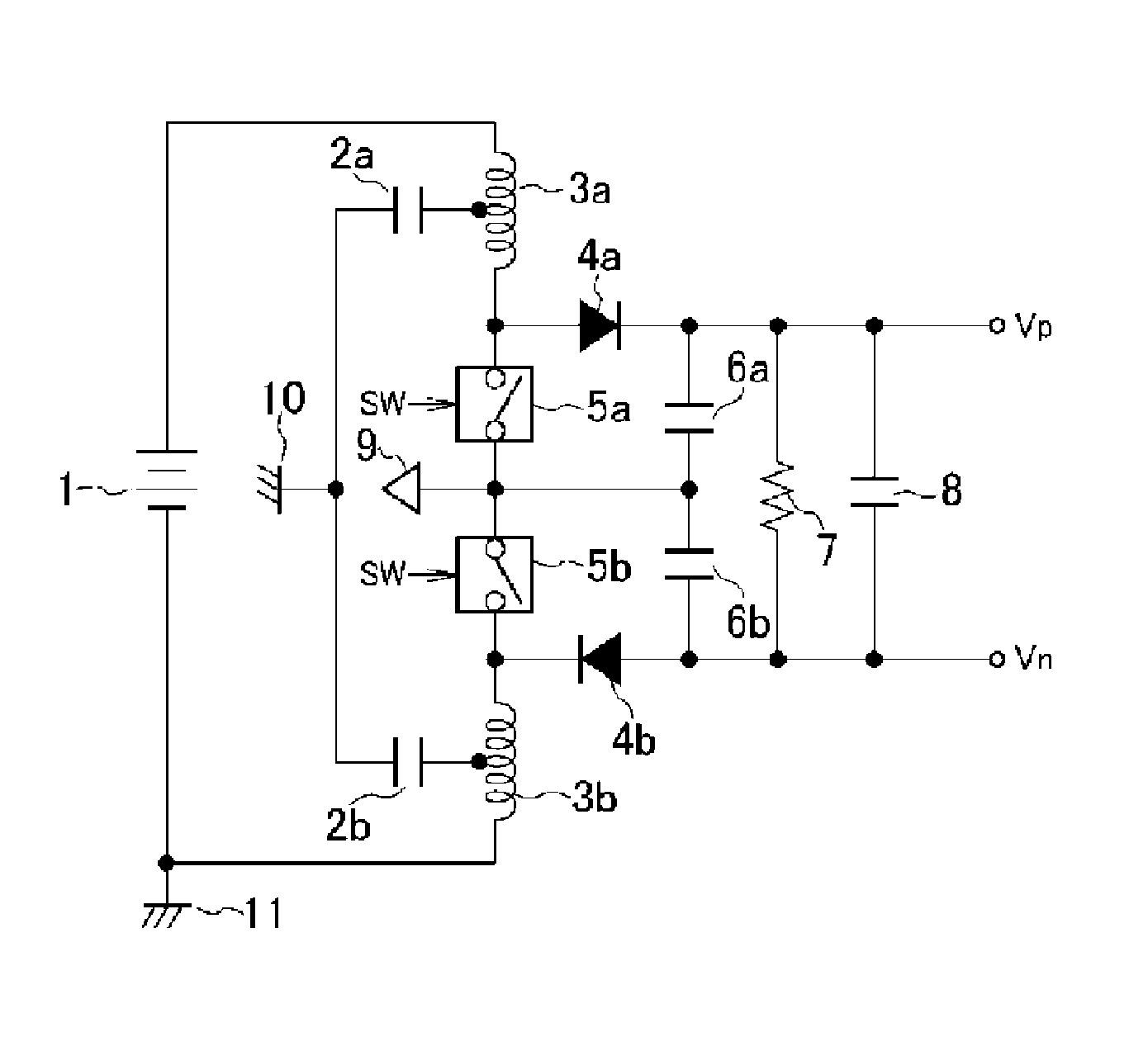
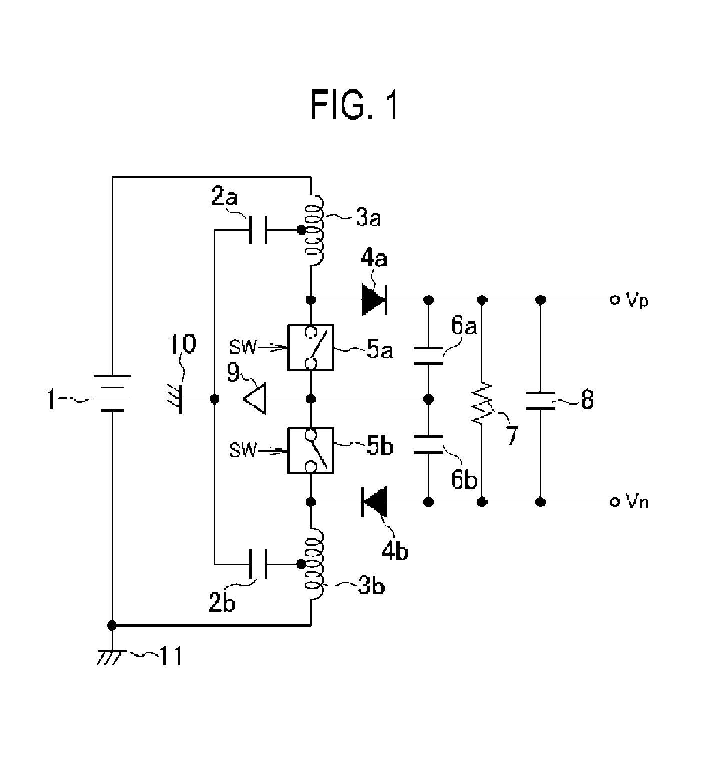
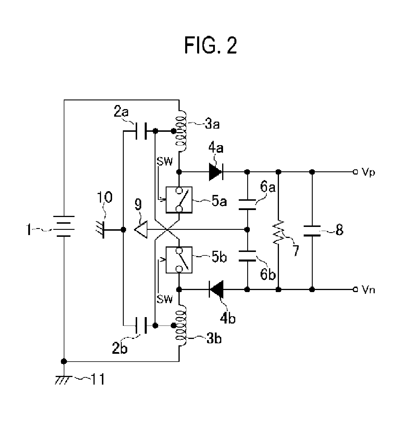
A switching power supply device includes: a positive voltage output circuit connected to a direct-current power supply, the positive voltage output circuit including a first switching element, a voltage boosting inductor, a first rectifying element and a first capacitor; a negative voltage output circuit connected to the power supply, the negative voltage output circuit including a second switching element, a voltage dropping inductor, a second rectifying element and a second capacitor; and an adder circuit configured to add switching currents flowing when the first and the second switching elements are operated. The circuit elements of the positive voltage output circuit are symmetrical with those of the negative voltage output circuit. The first switching current of the positive voltage output circuit and the second switching current of the negative voltage output circuit are generated in mutually opposite directions and are inputted to the adder circuit.

Description

CROSS-REFERENCE TO RELATED APPLICATION[0001]This application is based upon and claims the benefit of priority from Japanese Patent Application No. 2011-028674, filed on Feb. 14, 2011, the entire contents of which are incorporated herein by reference.TECHNICAL FIELD[0002]The present disclosure relates to a switching power supply device having a noise reduction function.BACKGROUND[0003]A switching power supply device of the related art has a configuration in which a pulse voltage is generated from an input voltage by a switching operation and an output voltage is obtained by smoothing the pulse voltage. In the switching power supply device, it is possible to obtain a desired positive voltage and a desired negative voltage. The efficiency of the obtained voltages is as high as 80% to 95%. Thus, the switching power supply device is superior from the viewpoint of power-saving design.[0004]However, if a wireless communication unit for processing ultra-micro signals, such as Bluetooth, GPS...

Claims


Application Information

Patent Timeline
Patent Type & Authority Patents(United States)
IPC IPC(8): H02M3/156H02M1/44H02M3/158
CPCH02M3/156H02M1/44H02M3/158
Inventor INAGAKI, RYOSUKE
Owner ROHM CO LTD
Learn More