Conveyor Belt Monitoring System

a monitoring system and conveyor belt technology, applied in the direction of conveyor control devices, conveyor parts, transportation and packaging, etc., can solve the problems of inability to apply monitoring systems to existing conveyor belts, inability to accurately determine the meander width at a desired position between pulleys with maximum meander width, and the conveyor belt to be likely to meander. , to achieve the effect of accurately reducing the meander width of the conveyor belt, and high versatility

Active Publication Date: 2019-11-21
THE YOKOHAMA RUBBER CO LTD
View PDF0 Cites 2 Cited by
  • Summary
  • Abstract
  • Description
  • Claims
  • Application Information

AI Technical Summary

Benefits of technology

[0005]The present technology provides a monitoring system with high versatility, capable of accurately reducing a meander width while sequentially determining a running state and a state of a conveying object at a desired position of a conveyor belt in its longitudinal direction.
[0006]A conveyor belt monitoring system according to an embodiment of the present technology includes a meander detecting device that detects a meander width of a conveyor belt in running, a control unit that receives detection data acquired by the meander detecting device, and a meander suppressing device controlled by the control unit. The meander detecting device is an imaging device that sequentially images a longitudinal predetermined range of the conveyor belt from above, and includes a monitor in which image data imaged by the imaging device is displayed. The control unit receives the image data as the detection data to cause the meander suppressing device to reduce a meander width of the conveyor belt on the basis of the image data.
[0008]The control unit causes the meander suppressing device to reduce a meander width of the conveyor belt on the basis of the image data. Accordingly, the present technology does not require a special processing to be applied to a conveyor belt, so the monitoring system has very high versatility to be easily applied to an existing conveyor belt. In addition, a meander width at a desired position of the conveyor belt in its longitudinal direction is determined to reduce the meander width, and thus causes an advantage in accurately suppressing the meander width.

Problems solved by technology

Variation in the tension causes the conveyor belt to be likely to meander.
Unfortunately, this method detects a meander width of the conveyor belt at the pulley, so a meander width at a desired position between pulleys with maximum meander width cannot be accurately determined.
Thus, the monitoring system cannot be applied to an existing conveyor belt.
Thus, a meander state of the conveyor belt at a desired position in its longitudinal direction cannot be accurately determined.
In addition, a state of a conveying object loaded on the conveyor belt also cannot be determined.

Method used


Image

  • Conveyor Belt Monitoring System
  • Conveyor Belt Monitoring System
  • Conveyor Belt Monitoring System

Examples


Embodiment Construction

[0016]A conveyor belt monitoring system according to embodiments of the present technology will be described below with reference to the drawings.

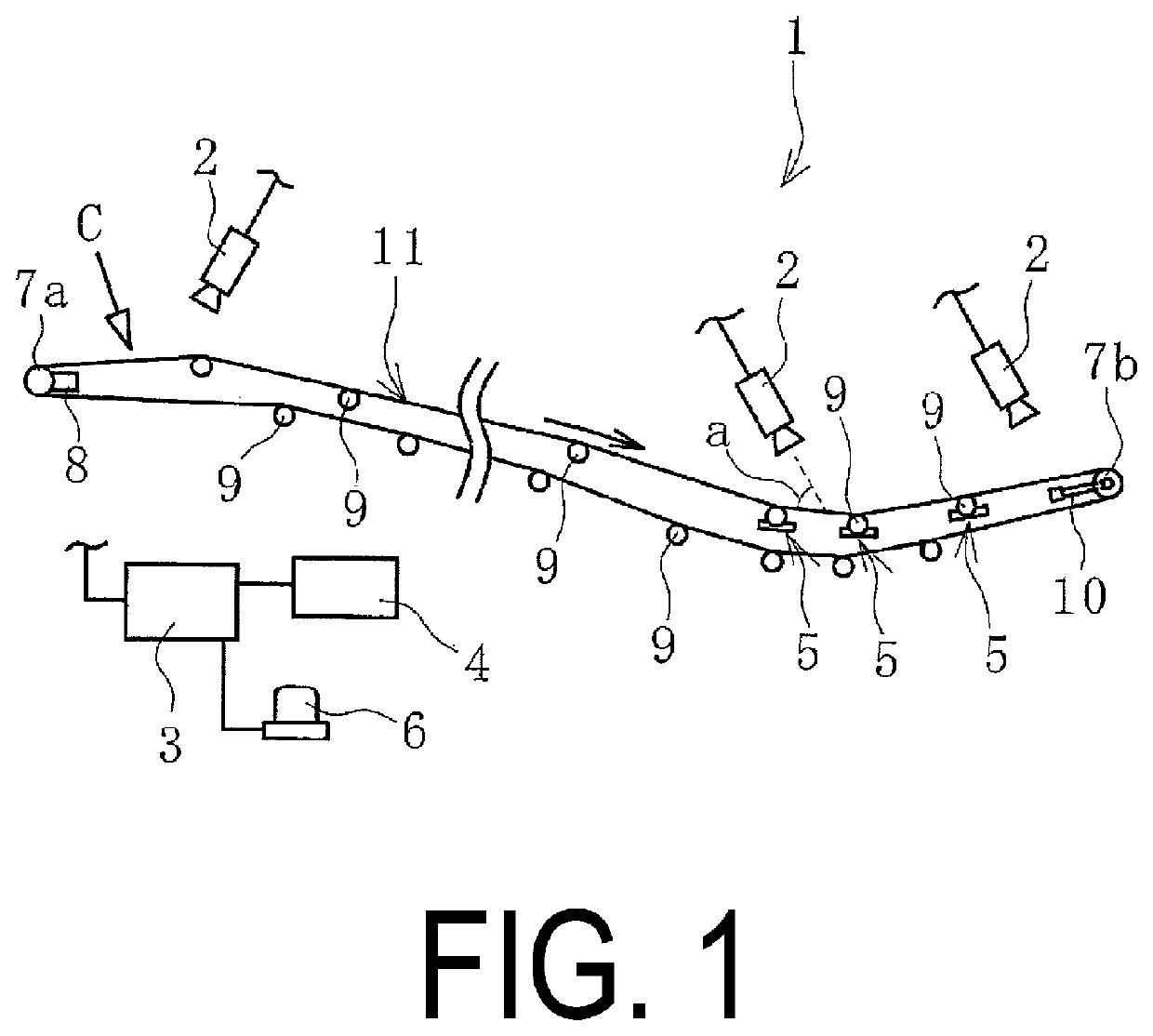
[0017]A conveyor belt wear monitoring system 1 (hereinafter referred to as “system 1”) of an embodiment of the present technology illustrated in FIG. 1 is to be applied to a conveyor belt 11 of a functioning conveyor belt line. In the system 1, a meander width Z is suppressed, and a running state of the conveyor belt 11 at a desired position in its longitudinal direction and a state of a conveying object C are sequentially determined. The meander width Z is a misalignment amount of the conveyor belt 11 in its lateral direction. The meander width Z is a numeric value indicating the extent of lateral displacement of the conveyor belt 11 with reference to the conveyor belt 11 in a state where the lateral center of the conveyor belt 11 is aligned with the lateral center of the conveyor belt line (normal state).

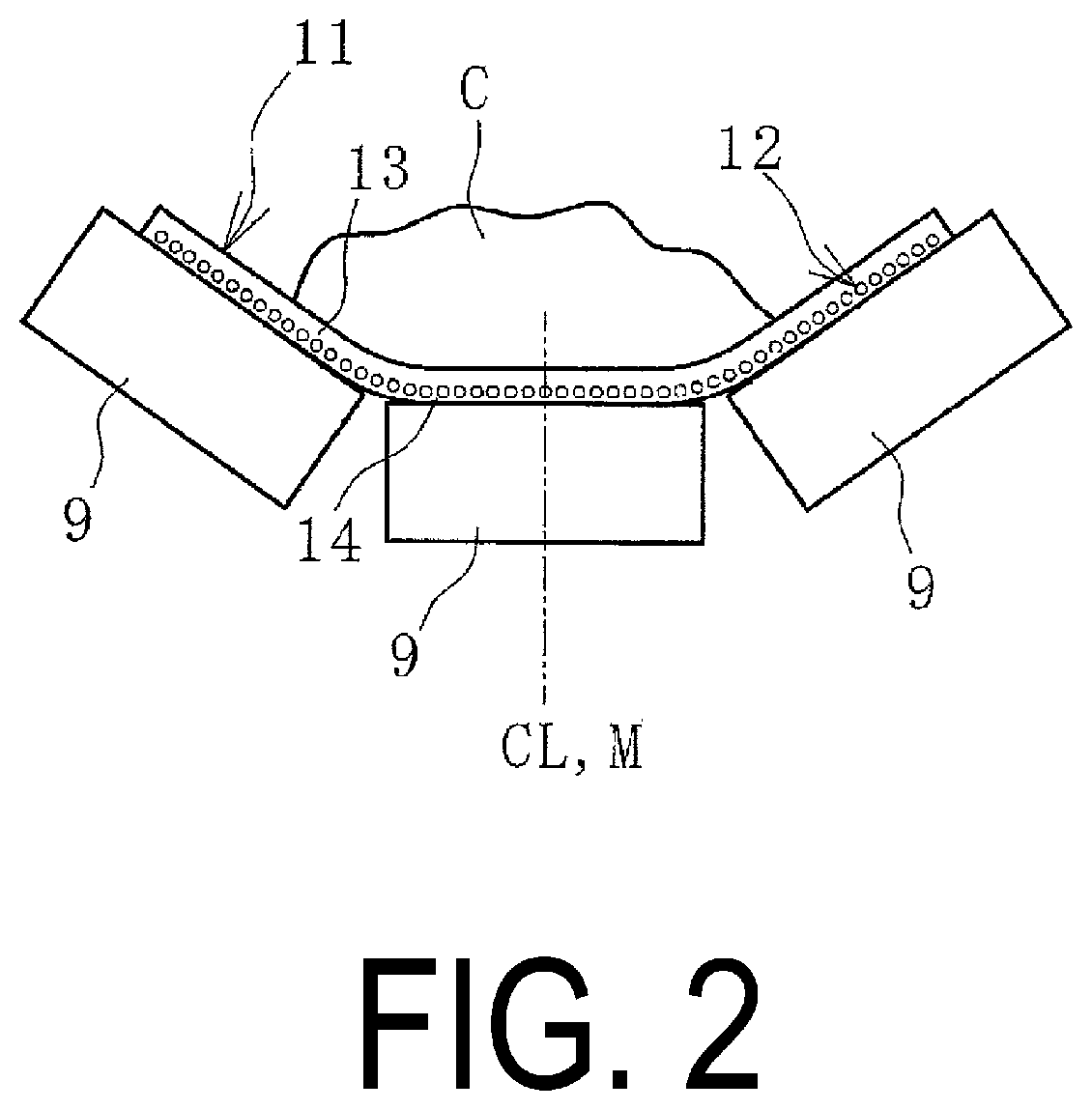
[0018]As illustrated in FIG. 2, t...


PUM


Abstract

A conveyor belt monitoring system includes an imaging device which sequentially images a longitudinal predetermined range of a conveyor belt in running from above the conveyor belt. Image data captured by the imaging device is displayed in a monitor, and then is sequentially input into a control unit as detection data. The control unit causes a meander suppressing device to reduce a meander width of the conveyor belt on the basis of the image data.

Description

TECHNICAL FIELD[0001]The present technology relates to a conveyor belt monitoring system and particularly relates to a monitoring system with high versatility, capable of accurately reducing a meander width, while sequentially determining a running state and a state of a conveying object at a desired position of a conveyor belt in its longitudinal direction.BACKGROUND ART[0002]Various objects, including mineral resources such as iron ore and limestone, are conveyed by a conveyor belt. The conveying objects are fed onto an upper cover rubber of the conveyor belt from a hopper or another conveyor belt. Tension acting on the conveyor belt varies due to a change of the conveying objects fed in terms of loaded weight, loaded position, and the like. Variation in the tension causes the conveyor belt to be likely to meander. Excessive meander width of the conveyor belt causes a conveying object to drop off and the conveyor belt to be damaged, so it is desirable to reduce the meander width.[...

Claims


Application Information

Patent Timeline
Patent Type & Authority Applications(United States)
IPC IPC(8): B65G15/64B65G43/02
CPCB65G43/02B65G15/64
Inventor HOU, GANGMIYAMOTO, MASAHIKOTAKAHASHI, TAROMANISHI, MASAHARUKOBAYASHI, EIJIINDO, HITOSHI
Owner THE YOKOHAMA RUBBER CO LTD
Why Eureka
Try Eureka