Stator for rotary electric motor

a technology of rotary electric motors and winding coils, which is applied in the direction of dynamo-electric machines, ac commutators, electrical apparatus, etc., can solve the problems of increasing cost, unfavorable clearance between the adjacent teeth at the inner peripheral side of the stator, and difficulty in changing the cross-sectional shape of the coil in the lengthwise direction, so as to improve the coil space factor of the stator, simple and convenient construction

Active Publication Date: 2015-07-02
TOYOTA JIDOSHA KK
View PDF6 Cites 15 Cited by
  • Summary
  • Abstract
  • Description
  • Claims
  • Application Information

AI Technical Summary

Benefits of technology

[0007]In light of the foregoing problem, the invention provides a stator for a rotary electric machine which has an improved coil space factor while having a simple and convenient construction.
[0012]The stator for a rotary electric machine of the invention as described above achieves an effect of being able to improve the coil space factor of the stator while employing a simple and convenient construction.

Problems solved by technology

In the case where a thick flat rectangular wire is wound around a tooth so as to form a coil of a single layer of winding, it is difficult to change the cross-sectional shape of the coil in the lengthwise direction of the tooth, which gives rise to a problem of the clearance between the coils of adjacent teeth being unfavorably small at the inner peripheral side of the stator, unlike the case where a round wire is wound around a tooth so as to form a coil of a plurality of layers of winding.
However, the coil described in JP 2001-178051 A requires that the cross-sectional shape and the cross-sectional area of conducting wires that form the coil be changed every turn of the winding, giving rise to a problem of complication of the shape of the winding wire and therefore an increase in cost.

Method used


Image

  • Stator for rotary electric motor
  • Stator for rotary electric motor
  • Stator for rotary electric motor

Examples


first embodiment

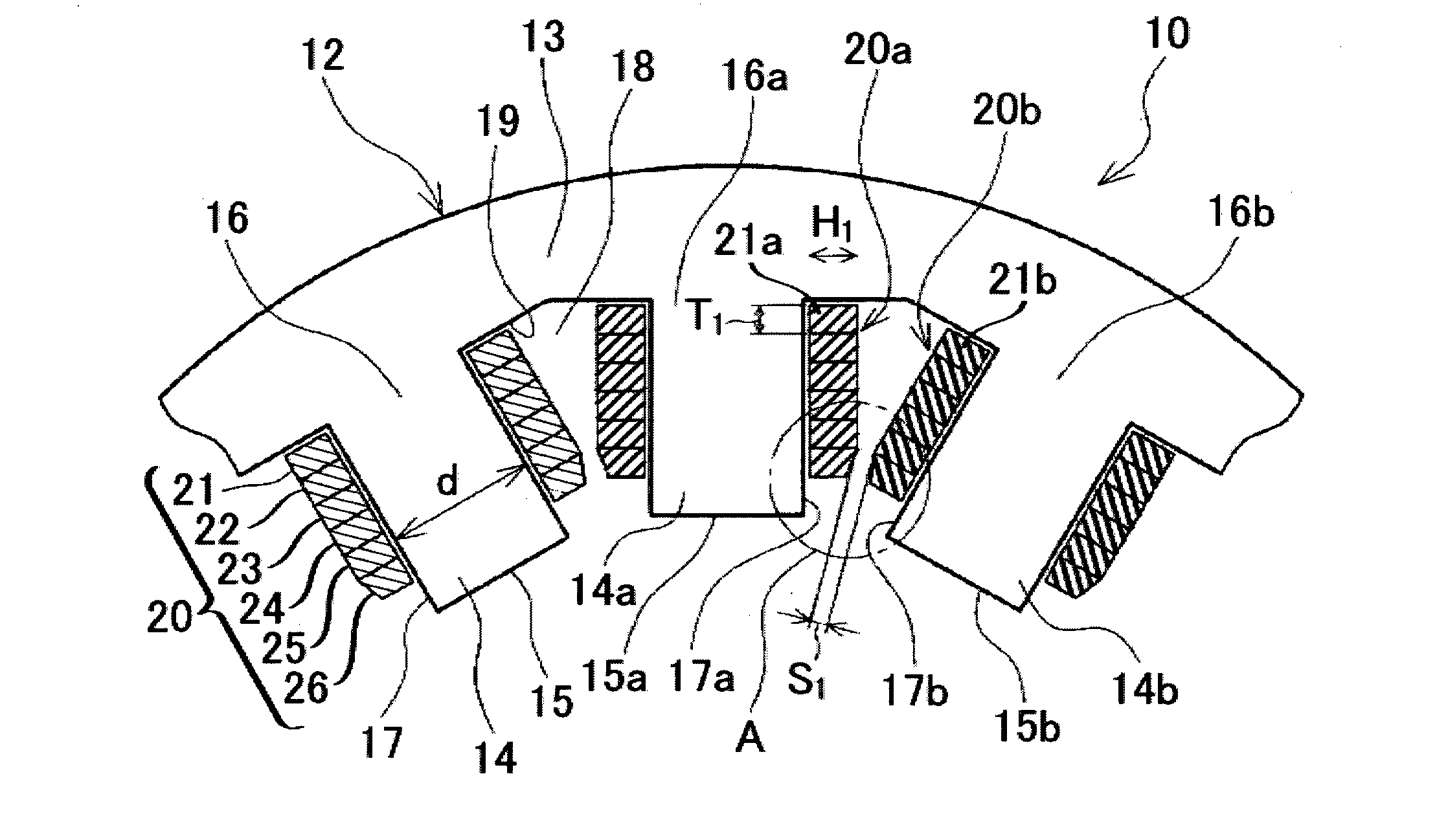
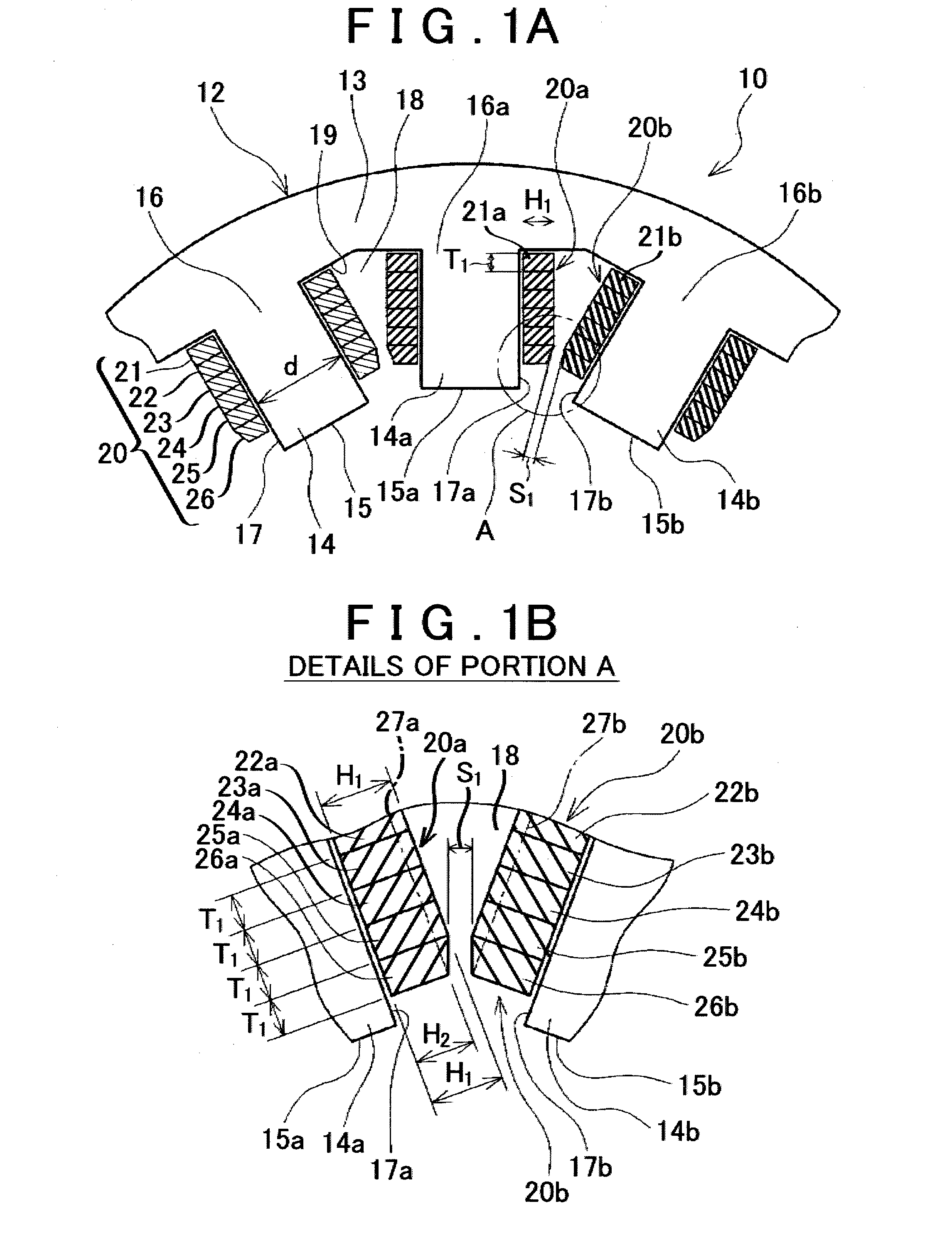
[0023]As shown in FIG. 1B, in the first embodiment, a concentrated winding coil 20a wound around a tooth 14a shown on the left side in the drawing is made up of two kinds of turns, one of the kinds including the first to fifth turns and the other kind including the sixth turn. The first to fifth turns on the tooth 14a are made by winding conducting wires 21a to 25a that are portions of a flat rectangular wire whose rectangular cross-section has a thickness T1 and a height H1 in such a winding manner that a side of the rectangular cross-sectional shape which corresponds to the thickness T1 faces a slot 18-side surface 17a of the tooth 14a and the sides of the height H1 extend from the surface 17a in a perpendicular direction. The sixth turn on the tooth 14a is made by winding a conducting wire 26a whose cross-sectional shape is a trapezoid that has a thickness T1 and a height H1 at a root end 16a side of the tooth 14a and a height H2 at a top end 15a side of the tooth 14a which is lo...

second embodiment

[0033]The foregoing second embodiment achieves an effect of being able to improve the coil space factor of the stator 10 and therefore effectively reduce loss while restraining cost increase by employing an easy and convenient method in which each of the sixth-turn conducting wires 26 is provided with a pentagonal cross-sectional shape obtained by cutting out a top end 15-side corner portion of the cross-section of the sixth-turn winding wire 26 and therefore the height of the sixth-turn conducting wires 26 is lower than the height of the other, i.e., first to fifth-turn, conducting wires 21 to 25.

[0034]Incidentally, although in the foregoing second embodiment, the interval between the mutually confronting faces of the conducting wires 26a and 26b consistently remains the least interval S3 over the dimension (width) of the mutually confronting faces in the radial direction of the stator, it is also permissible to adopt a construction in which the height H4 of the conducting wires 26...

third embodiment

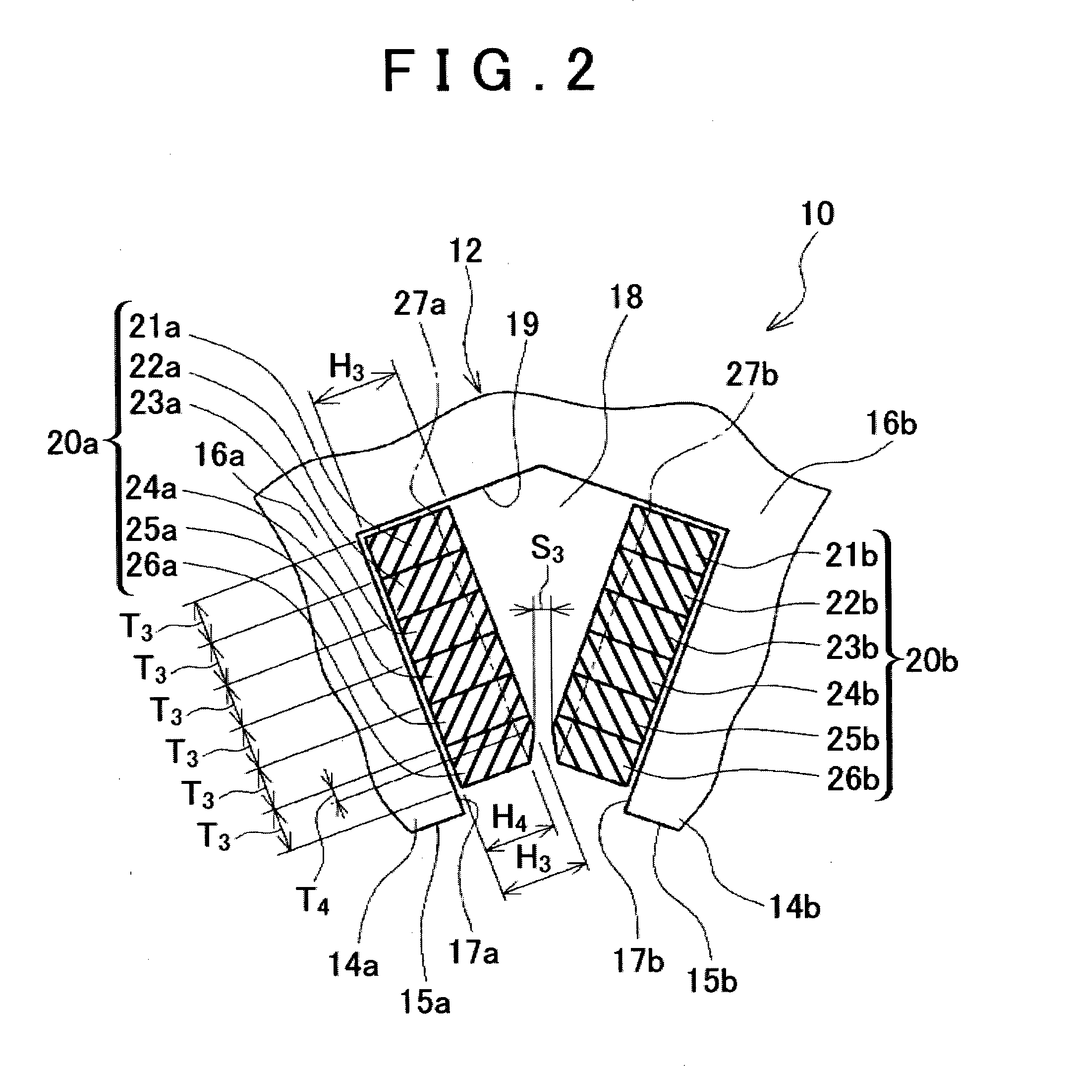
[0037]That is, in the third embodiment, in the concentrated winding coil 20a shown on the left side in FIG. 3, the conducting wires 24a to 26b of the three turns (fourth to sixth turns) on the top end 15a-side portion of the tooth 14a, except for the thickness T6 portion of the conducting wire 24a of the fourth turn, is lower than the common height H5 of the conducting wires 21a to 23a of the other turns (first to third turns). Furthermore, the height of the fifth-turn conducting wire 25a is less than the height of the fourth-turn conducting wire 24a, which is adjacent to the tooth root end 16a side of the fifth-turn conducting wire 25a. Further, the height of the sixth-turn conducting wire 26a is less than the height of the fifth-turn conducting wire 25a, which is adjacent to the tooth root end 16a side of the sixth-turn conducting wire 26a. The heights of the first to third-turn conducting wires 21a to 23a are substantially equal, and are higher than the heights of the fourth to s...


PUM


Abstract

A stator for a rotary electric machine has a tooth whose width in a circumferential direction is substantially constant in a radial direction of the stator, and a concentrated winding coil including winding conducting wires around the tooth. A height of a first conducting wire of the sixth turn at a tooth's top end side measured from a surface of the tooth is lower than a height of a conducting wire adjacent to a tooth's root end side of the conducting wire measured from the tooth surface. Conducting wires of the first to fifth turns, that is, second conducting wires, have the same height from the surface of the tooth.

Description

BACKGROUND OF THE INVENTION[0001]1. Field of the Invention[0002]The invention relates to a structure of a concentrated winding coil provided on a stator of a rotary electric machine.[0003]2. Description of Related Art[0004]In order to reduce the loss of an electric motor, it is effective to increase the coil space factor (conductor's cross-sectional area / coil's cross-sectional area) of the stator. Therefore, a structure in which thick flat rectangular wires whose cross-sectional shape is rectangular, as conducting wire for forming coils, are wound around the teeth so that each tooth has thereon a single layer of winding is more often employed than a structure in which round wires whose cross-sectional shape is round are wound around the teeth so that each tooth has thereon a plurality of layers of winding. In the meantime, a construction of a stator in which each of the teeth extends radially inward and the width of each tooth in the circumferential direction (the circumferential wi...

Claims


Application Information

Patent Timeline
Patent Type & Authority Applications(United States)
IPC IPC(8): H02K3/12
CPCH02K3/12H02K3/18H02K2213/03H02K15/045
Inventor KATO, HIROKI
Owner TOYOTA JIDOSHA KK
Why Eureka
Try Eureka