Transmission stabilization device applied to dual-shaft system

a technology of transmission stabilization device and dual shaft, which is applied in the direction of electrical apparatus casing/cabinet/drawer, instruments, etc., can solve the problems of transmission block not being able to smoothly drive the second rotary shaft to synchronous rotation, transmission will be retarded, transmission structure wear, etc., to reduce component wear and stabilize the transmission. , the effect of smoothening the transmission

Active Publication Date: 2015-07-02
FIRST DOME
View PDF21 Cites 29 Cited by
  • Summary
  • Abstract
  • Description
  • Claims
  • Application Information

AI Technical Summary

Benefits of technology

[0009]It is therefore a primary object of the present invention to provide a transmission stabilization device applied to dual-shaft system for stabilizing and smoothening the transmission and reducing wear of the components. The transmission stabilization device includes a first rotary shaft, a second rotary shaft and a transmission unit, which are assembled with each other. Each of the first and second rotary shafts has a fixed section mounted on an electronic apparatus, a pivoted section assembled with a torque module and a connection section. The transmission unit is drivingly engaged with the connection sections. The transmission unit is mounted on a fixing shaft. When the first or second rotary shaft rotates, the transmission unit is moved along the fixing shaft with the rotation of the first or second rotary shaft. The transmission stabilization device can prevent two ends of the transmission unit from swinging so as to overcome the problem of retardation of transmission of the conventional device.

Problems solved by technology

This will cause wear of the transmission structure.
Also, the transmission block can hardly smoothly drive the second rotary shaft to synchronously rotate.
As a result, the transmission will be retarded and the electronic apparatus can be hardly smoothly operated and rotated.

Method used


Image

  • Transmission stabilization device applied to dual-shaft system
  • Transmission stabilization device applied to dual-shaft system
  • Transmission stabilization device applied to dual-shaft system

Examples


Embodiment Construction

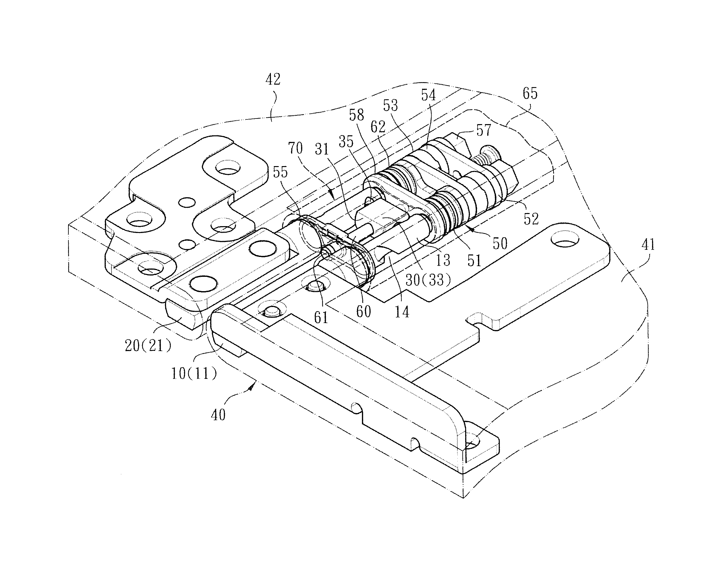
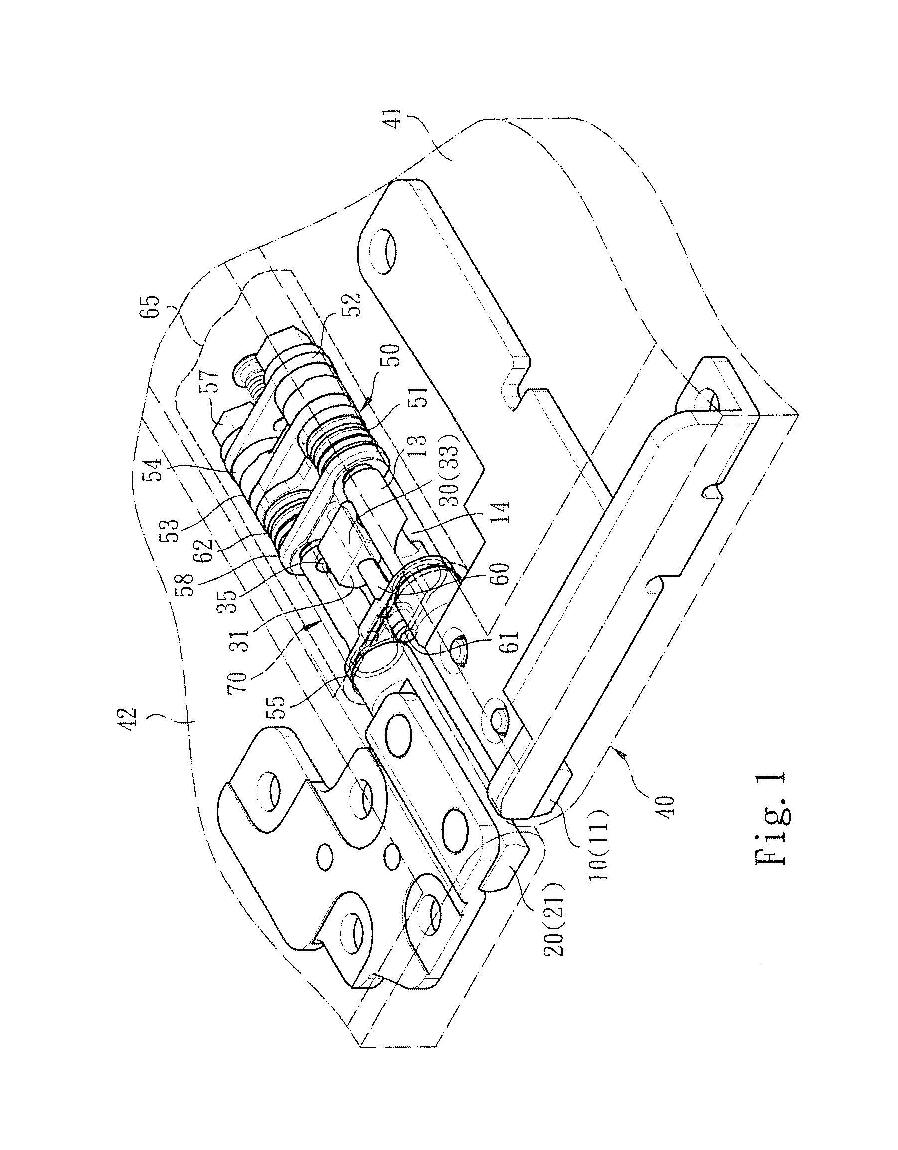
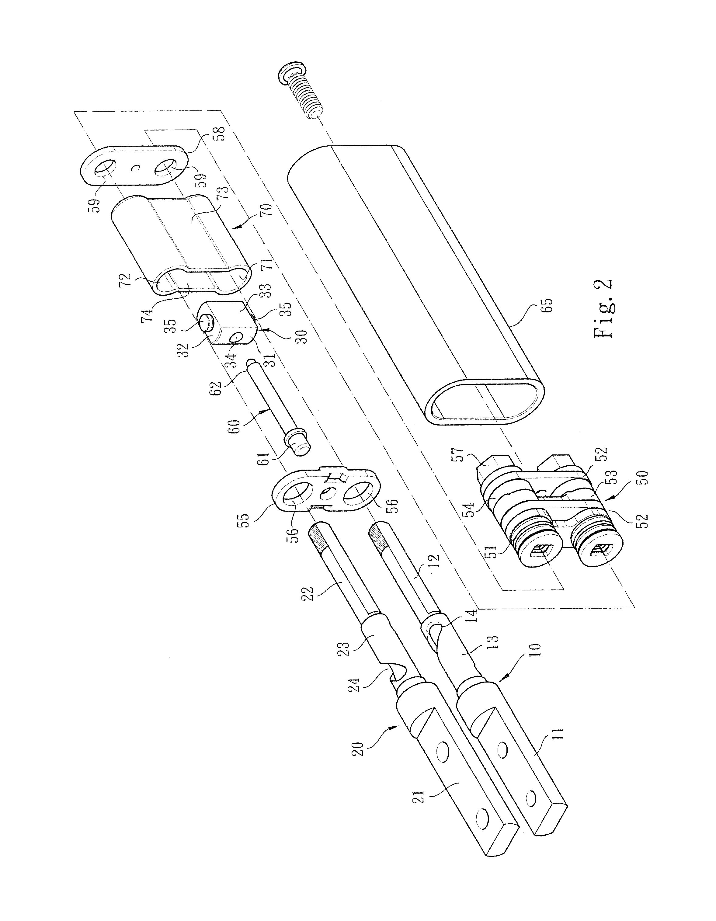
[0016]Please refer to FIGS. 1, 2 and 3. According to a preferred embodiment, the transmission stabilization device applied to dual-shaft system of the present invention is assembled with an electronic apparatus (such as a computer) for illustration purposes. The transmission stabilization device includes a first rotary shaft 10, a second rotary shaft 20 and a transmission unit 30, which are assembled with each other. Each of the first and second rotary shafts 10, 20 has a fixed section 11, 21, a pivoted section 12, 22 and a connection section 13, 23 positioned between the fixed section 11, 21 and the pivoted section 12, 22.

[0017]The fixed section 11 of the first rotary shaft is connected with and disposed on an apparatus body module 41 of the electronic apparatus 40. The fixed section 21 of the second rotary shaft is connected with and disposed on a display module 42 of the electronic apparatus 40. The pivoted sections 21, 22 of the first and second rotary shafts 10, 20 are (respect...


PUM


Abstract

A transmission stabilization device applied to dual-shaft system for stabilizing and smoothening the transmission and reducing wear of the components. The transmission stabilization device includes a first rotary shaft, a second rotary shaft and a transmission unit, which are assembled with each other. Each of the first and second rotary shafts has a fixed section mounted on an electronic apparatus, a pivoted section assembled with a torque module and a connection section. The transmission unit is drivingly engaged with the connection sections. The transmission unit is mounted on a fixing shaft. When the first or second rotary shaft rotates, the transmission unit is moved along the fixing shaft with the rotation of the first or second rotary shaft. The transmission stabilization device can prevent the transmission unit from swinging so as to overcome the problem of retardation of transmission of the conventional device.

Description

BACKGROUND OF THE INVENTION[0001]1. Field of the Invention[0002]The present invention relates generally to a transmission stabilization device applied to dual-shaft system, and more particularly to a transmission stabilization device, which is assembled with two rotary shafts of the dual-shaft system for stabilizing the transmission of the transmission unit.[0003]2. Description of the Related Art[0004]There are various electronic apparatuses provided with covers or display screens, such as mobile phones, notebooks, PDA, and electronic books. The covers or display screens are pivotally mounted on the electronic apparatuses via pivot pins or rotary shafts, whereby the covers or display screens can be freely rotated and opened / closed under external force.[0005]In order to operate the display module (such as the screen) and / or the apparatus body module of the electronic apparatus in more operation modes and application ranges, a dual-shaft mechanism is provided between the display modul...

Claims


Application Information

Patent Timeline
Patent Type & Authority Applications(United States)
IPC IPC(8): H05K5/02F16H57/021E05D3/06F16H25/06
CPCH05K5/0226E05D3/06F16H57/021F16H25/06E05D3/122G06F1/1681H04M1/022E05D3/12Y10T74/1836
Inventor HSU, AN SZU
Owner FIRST DOME
Why Eureka
Try Eureka