Method for producing a housing, especially a valve housing

a valve housing and production method technology, applied in the direction of machines/engines, magnetic bodies, applications, etc., to achieve the effect of avoiding short-circuit currents, improving magnetic separation, and reducing them

Inactive Publication Date: 2015-07-09
ROBERT BOSCH GMBH
View PDF5 Cites 1 Cited by
  • Summary
  • Abstract
  • Description
  • Claims
  • Application Information

AI Technical Summary

Benefits of technology

[0004]In contrast to the related art, the method of the present invention has the advantage that an improved magnetic separation is able to be realized in the magnetic circuit. This makes it possible to avoid magnetic short-circuit currents or at least reduce them, and to improve the efficiency factor of the magnetic circuit. For example, this may result in a considerable increase in the efficiency factor in s

Problems solved by technology

It is a challenge in the related art to manage a magnetic separation in a way that realize

Method used


Image

  • Method for producing a housing, especially a valve housing
  • Method for producing a housing, especially a valve housing
  • Method for producing a housing, especially a valve housing

Examples


Embodiment Construction

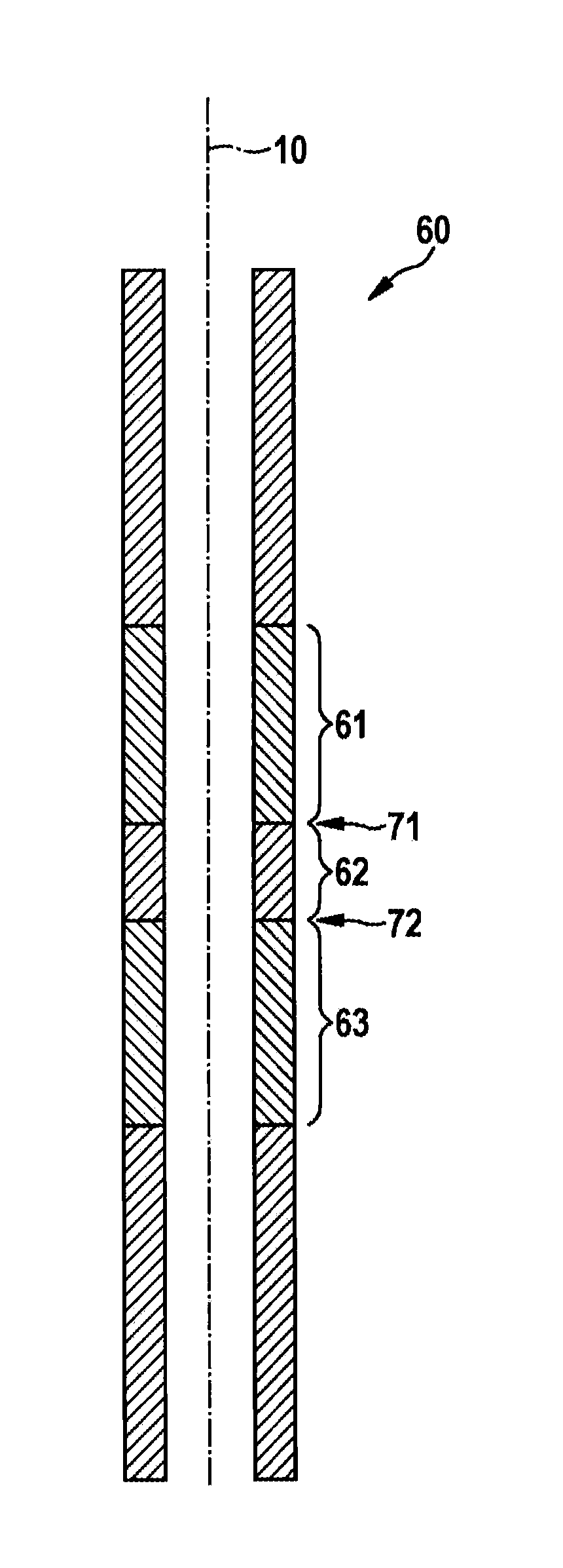
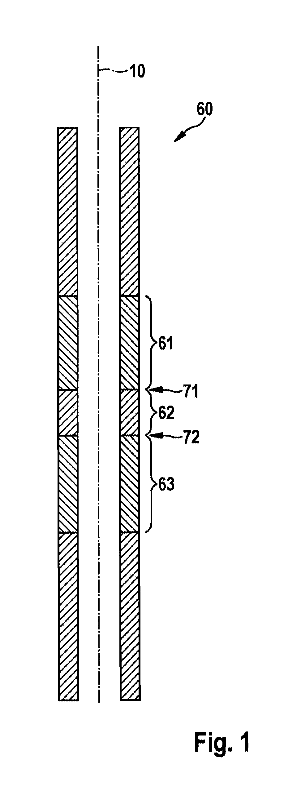
[0016]In the various figures, identical parts have always been provided with the same reference symbols and are therefore usually labeled or mentioned only once as a rule.

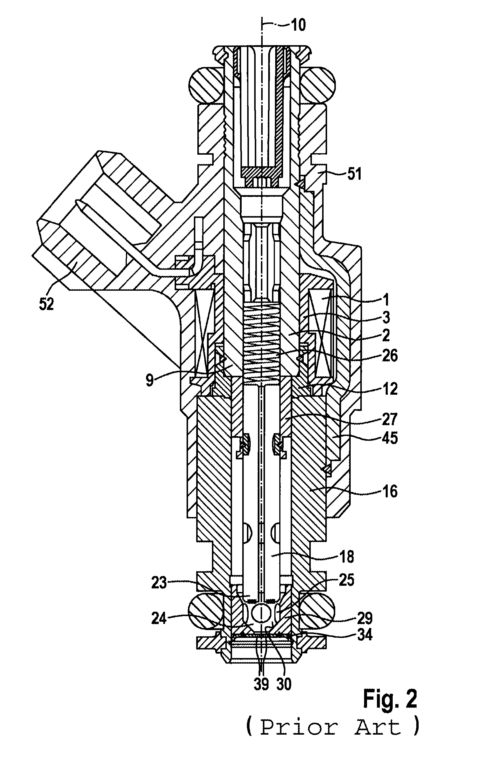
[0017]The electromagnetically operable valve in the form of a fuel injector known from the related art, which is shown in FIG. 2 by way of example and intended for fuel-injection systems of mixture-compressing, externally ignited or self-igniting internal combustion engines, has a tubular core 2, which is surrounded by a solenoid coil 1 and serves as fuel intake neck as well as an inner pole, core 2, for example, having a constant outer diameter over its entire length.

[0018]A coil shell 3 stepped in the radial direction accommodates a winding of solenoid coil 1 and, in conjunction with core 2, makes it possible for the fuel injector to have a compact design in the region of solenoid coil 1. A tubular, metallic nonmagnetic intermediate part 12 is sealingly connected by welding to a lower core end 9 of core 2, concen...


PUM

PropertyMeasurementUnit
Circumferenceaaaaaaaaaa

Abstract

A method for producing a housing is provided. In a first method step, connecting a material plate, having a main extension plane in each case, of the first, second and third material, respectively, in the first and second connection regions, the first and second connection region extending parallel to the main extension planes of the material plates in each case; in a second connection step, processing the interconnected material plates in order to produce the first, second and third zones of the housing.

Description

FIELD OF THE INVENTION[0001]The present invention relates to a method for producing the housing, especially a valve housing for an electromagnetically actuable valve.BACKGROUND INFORMATION[0002]Known from the related art, such as from the printed publication European Patent No. 169 9578 B1, for example, are valve housings, especially for fuel injectors, which have a classic three-part structure of an internal metallic flow guidance component and simultaneously housing part, this housing being formed by an intake nipple constituting an internal pole, a nonmagnetic intermediate part, and a valve seat support which accommodates a valve seat. In this case, the housing is known to have a hollow cylindrical metal housing, which has two magnetizable housing parts and an interposed amagnetic housing zone that magnetically separates the housing parts.[0003]It is a challenge in the related art to manage a magnetic separation in a way that realizes high effective selectivity between magnetic a...

Claims


Application Information

Patent Timeline
IPC IPC(8): B23P15/00
CPCB23P15/001F02M51/0671F02M59/445F02M61/168H01F7/081H01F7/128H01F7/1607H01F2007/085Y10T29/49412Y10T29/49419Y10T29/49423
Inventor WONDRACZEK, LUTZ
Owner ROBERT BOSCH GMBH
Why Eureka
Try Eureka