Energy Recycling Heat Pump

Active Publication Date: 2015-07-09
KELLEY CONSTANCE D +2
View PDF12 Cites 1 Cited by
  • Summary
  • Abstract
  • Description
  • Claims
  • Application Information

AI Technical Summary

Benefits of technology

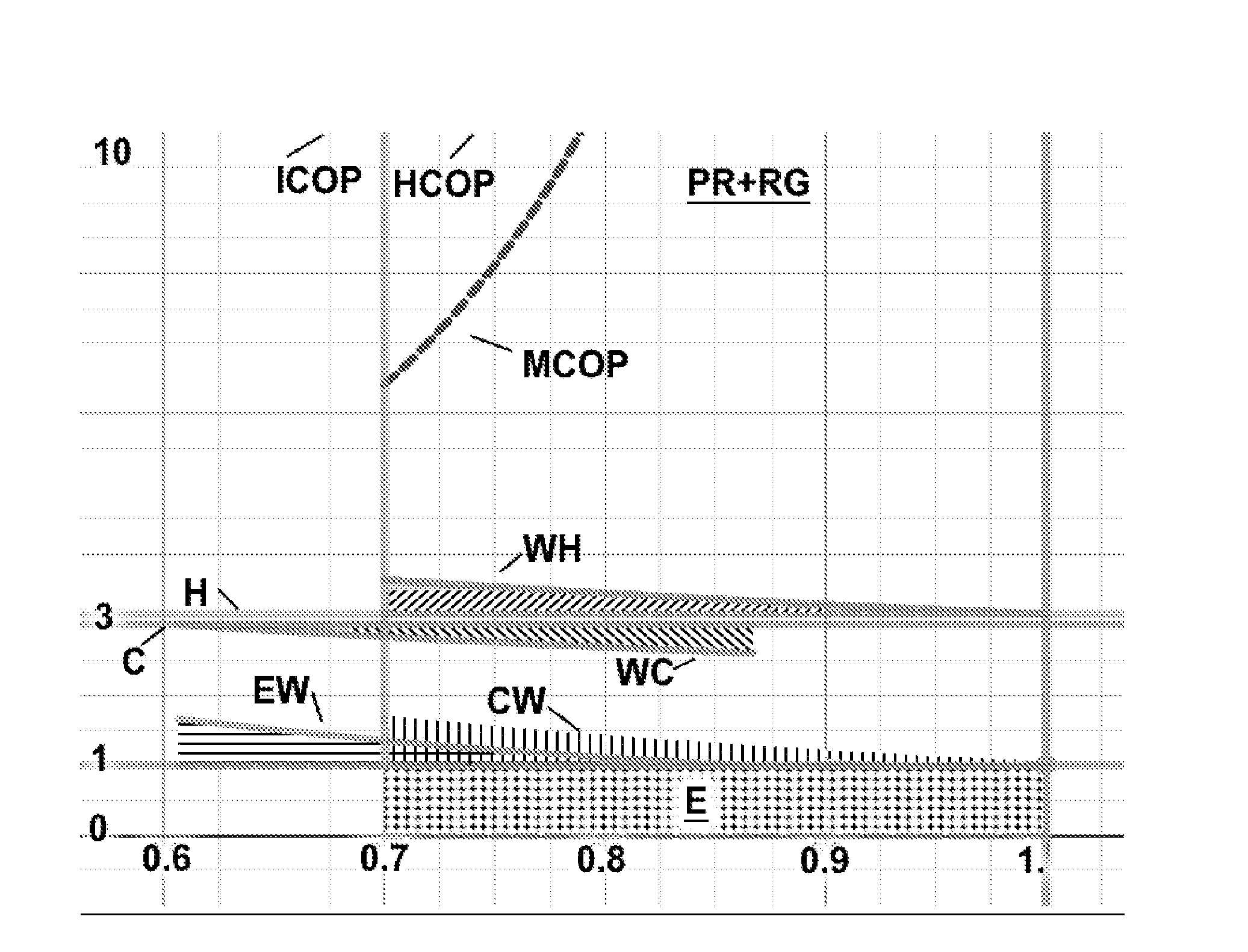
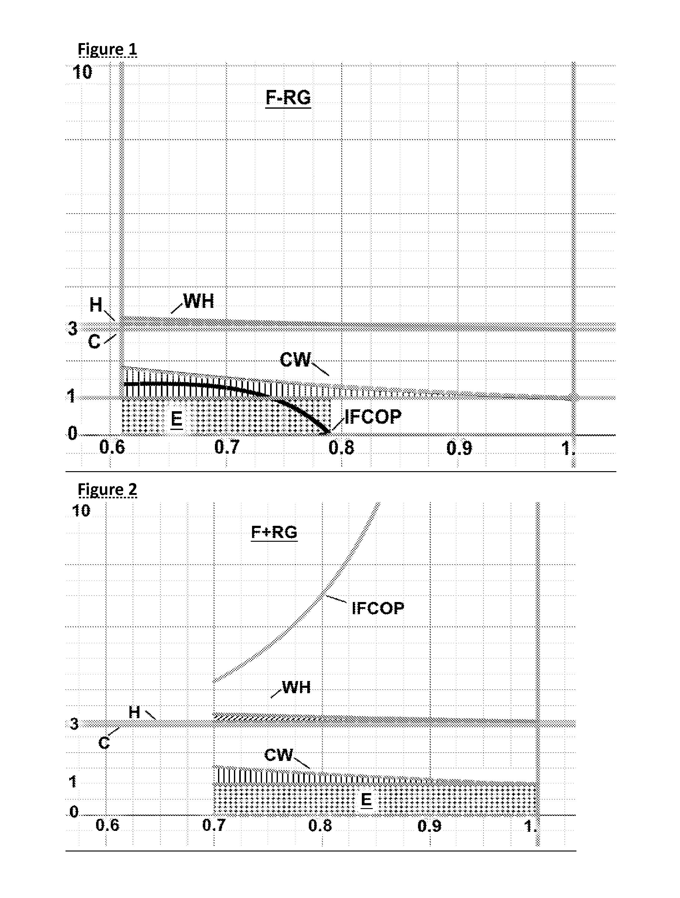
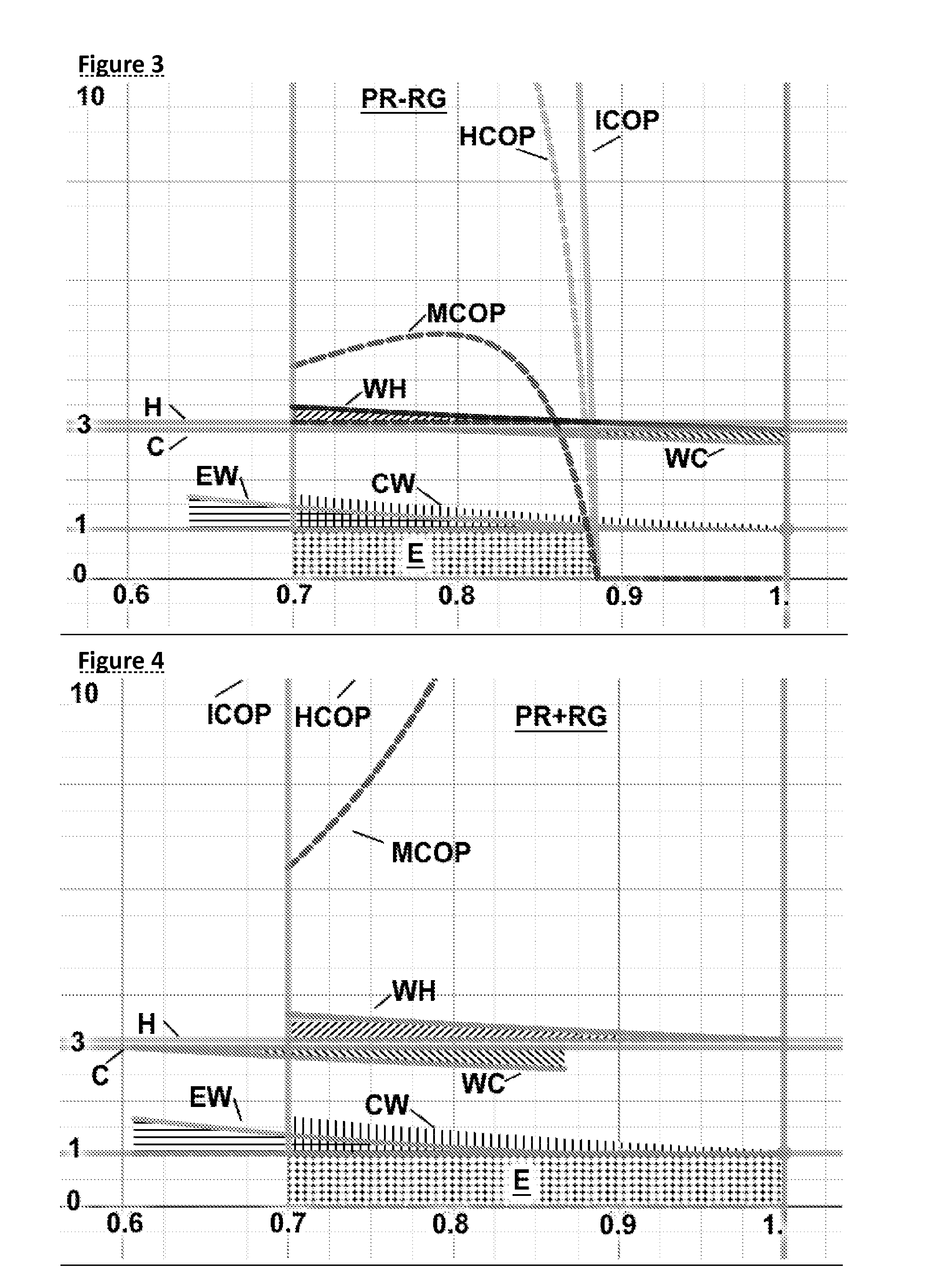
[0013]Additionally, the ratio of the added work to the pumped heat approaches 0% as smaller amounts of heat are moved, also causing the COP to increase and energy expenditure (energy of compress minus energy of air motor expansion) to approach 0. This effect and the pressure difference recycling are multiplicative, so the ideal COP increases quadratically as the amount of heat pumped per unit time decreases. System designs which can run continuously at lower rates of heat movement will be more efficient than system

Problems solved by technology

Refrigeration and heat pump systems use large amounts of energy and have limited range of temperature difference between the heat source/heat sink and the air or vapor being cooled or heated.
They have inherent limits of temperature range because of use of phase change to achieve temperature

Method used


Image

  • Energy Recycling Heat Pump
  • Energy Recycling Heat Pump
  • Energy Recycling Heat Pump

Examples


Example

[0055]The system is designed recognizing three facts about the thermodynamics of pumping heat.

[0056]First, the maximum efficiency (COP) will be achieved by operating at a minimum pressure difference.

[0057]Second, the work done in compression can be mirrored by a similar expansion device (piston, air motor or turbine), and in the ideal case would result in reducing work energy added to the system by (1−ratio of absolute temperatures). The work energy produced by the expansion device then remains in the system, and once operating does not need to be replaced. This allows an amount of energy equal to the work available from expansion to be recycled, and remains in the system via the coupling of the expansion and compression stages.

[0058]Third, in both Freon and air based systems, the working fluid leaving the cool space is at cool space's ambient temperature, and leaving the hot space is at the hot space's ambient temperature. This creates a temperature gap the working fluid must cross...


PUM


Abstract

A set of devices that can leverage creating small volume changes with small amount of work to create larger heat energy temperature differences, recycle a portion of the compression energy equal to approximately the ratio of the absolute temperature of the cooled space to the heated space, and recycle the heat energy to reduce or eliminate the effect of the temperature gap between the cooled space and heated space. Piston, rotary and turbine based devices are disclosed to achieve the recycled compression energy, for systems designed with single phase vapor or air working fluids. System configuration with counterflow heat exchanger disclosed to recycle the energy needed to cross the temperature gap, applicable both to air/vapor systems and to Freon/refrigerant 2 phase systems. Resulting single phase systems can operate over entire temperature range of Earth's surface and are not limited to constrained temperature range of refrigerant phase change.

Description

CROSS-REFERENCE TO RELATED APPLICATIONS[0001]Information on Freon 410 obtained from Patent US20100281915, Counterflow heat exchanger related application attorney docket wakelley01. This patent application replaces and supersedes patent application with attorney docket number wakelley07, which has been withdrawn.STATEMENT REGARDING FEDERALLY SPONSORED RESEARCH AND DEVELOPMENT[0002]This patent is not federally sponsored.REFERENCE TO SEQUENCE LISTING, A TABLE, OR A COMPUTER PROGRAM LISTING COMPACT DISC APPENDIX[0003]Not applicable.BACKGROUND OF THE INVENTION[0004]Refrigeration and heat pump systems use large amounts of energy and have limited range of temperature difference between the heat source / heat sink and the air or vapor being cooled or heated. They have inherent limits of temperature range because of use of phase change to achieve temperature shift. They also suffer from a “dead band” of wasted energy to create a temperature shift large enough to bridge the gap between the refr...

Claims


Application Information

Patent Timeline
IPC IPC(8): F25B27/00
CPCF25B27/00F25B11/02
Inventor KELLEY, WILLIAM A.
Owner KELLEY CONSTANCE D
Why Eureka
Try Eureka