Electrical connector

Inactive Publication Date: 2015-07-09
KONINKLJIJKE PHILIPS NV
View PDF10 Cites 1 Cited by
  • Summary
  • Abstract
  • Description
  • Claims
  • Application Information

AI Technical Summary

Benefits of technology

[0003]It is an object of the present invention to provide an electrical connector for connecting an electrical device to an electrical conduct

Problems solved by technology

This reduces the likelihood of a shutdown of the powering of the electr

Method used


Image

  • Electrical connector
  • Electrical connector
  • Electrical connector

Examples


Embodiment Construction

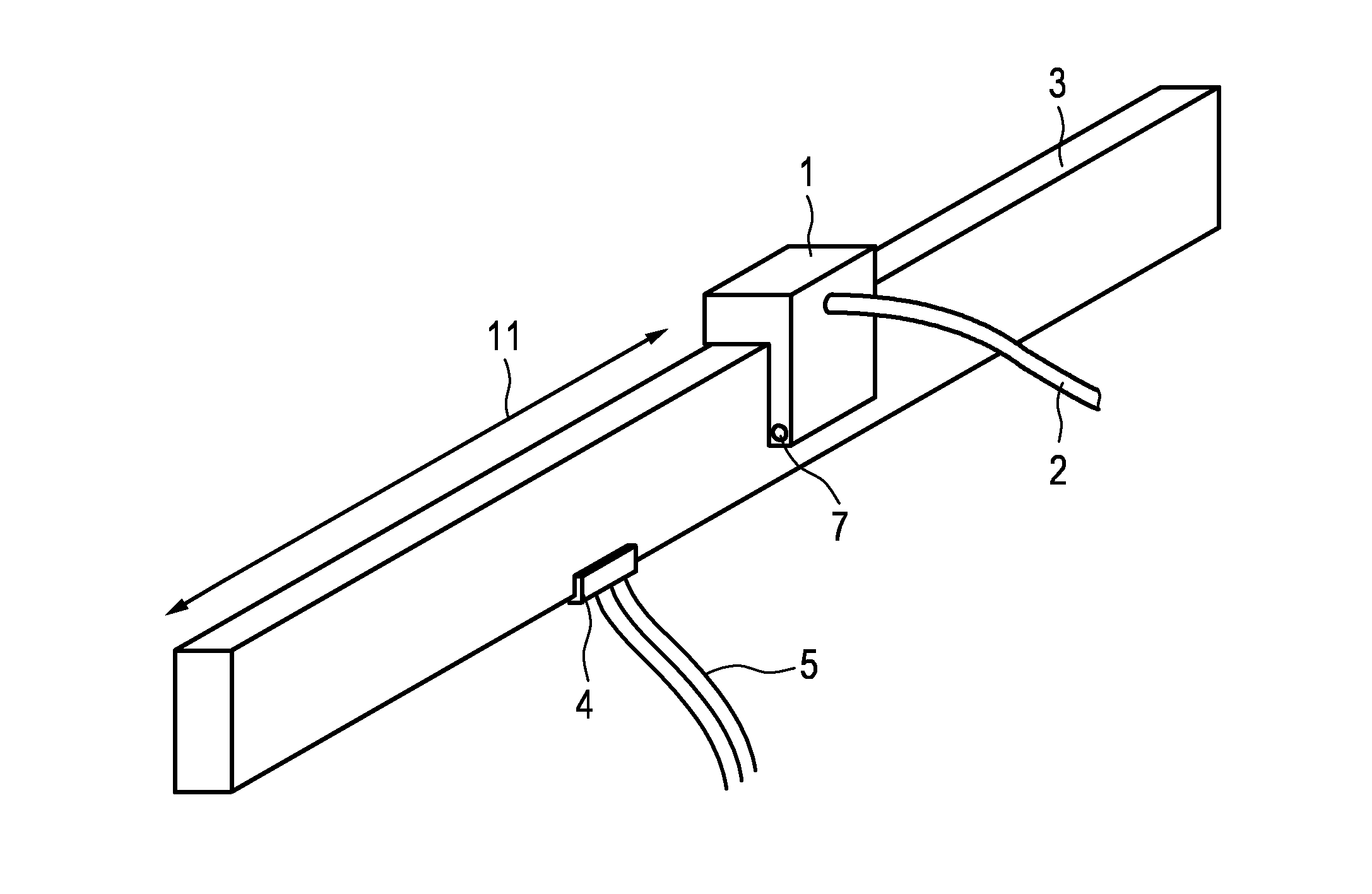
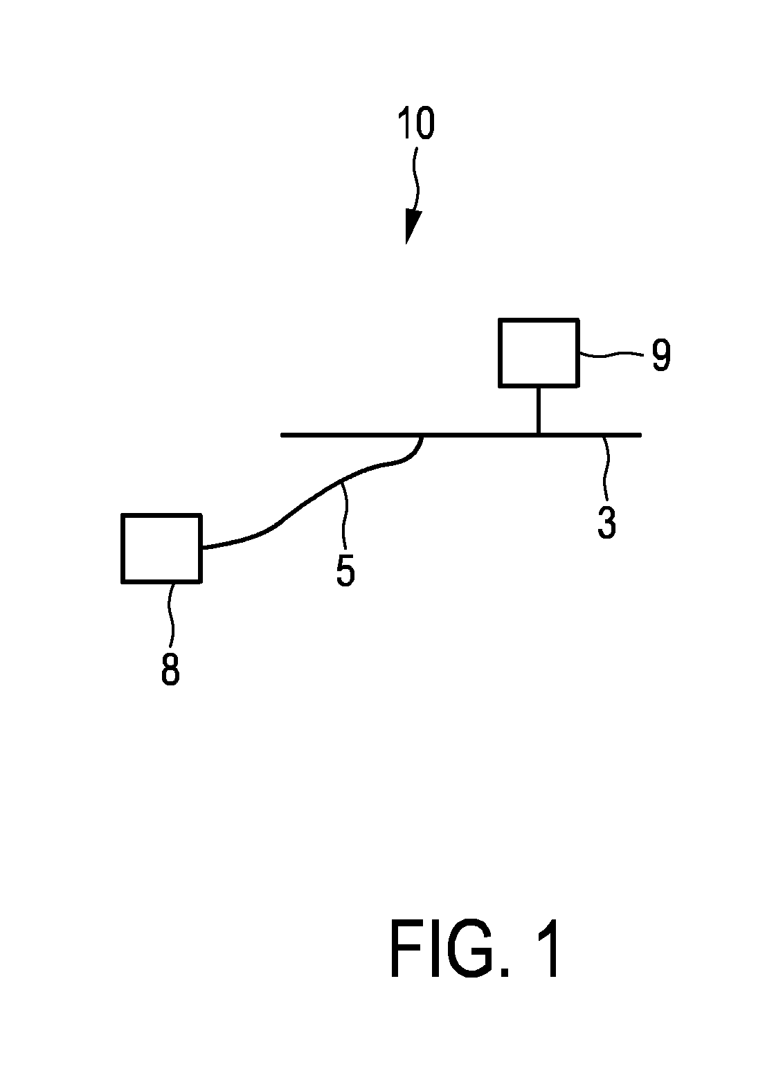
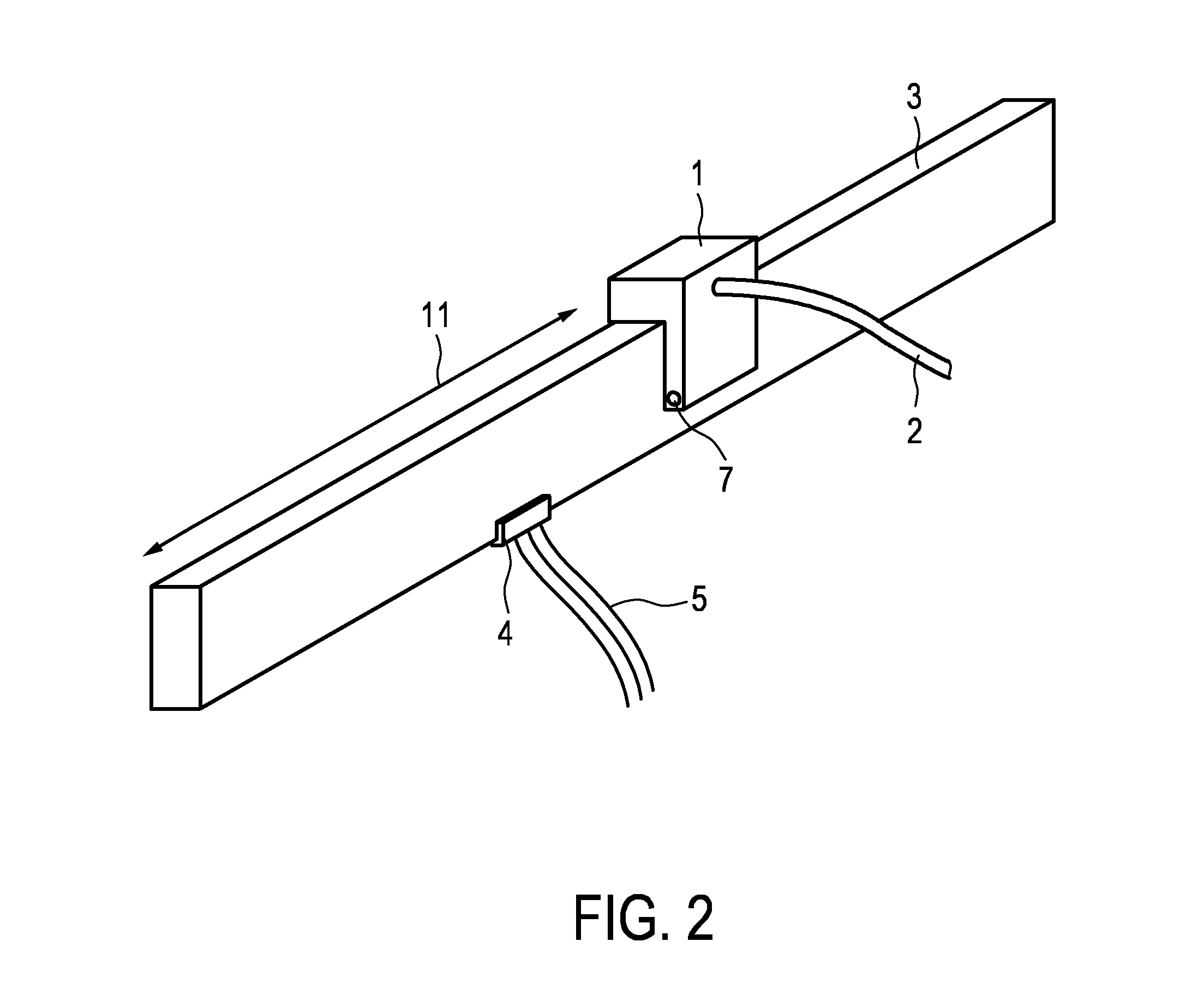
[0036]FIG. 1 shows schematically and exemplarily a DC power distribution system comprising a DC voltage source 8 being connected to an electrical conductor 3 via a cable 5, and an electrical device 9 like a lamp being connected to the electrical conductor 3. The connections are exemplarily and schematically shown in more detail in FIG. 2.

[0037]The cable 5 is electrically connected to the electrical conductor 3 via a feed connector 4, and the electrical device 9 is connected to the electrical conductor 3 via an electrical connector 1 and a further cable 2. The feed connector 4 is preferentially located at one third of the length of the electrical conductor 3. The electrical connector 1 is located on the electrical conductor 3 with a distance 11 from an end of the electrical conductor 3. The electrical connector 1 can be attached via the cable 2 to the electrical device 9 as shown in FIG. 2, or the electrical connector 1 can be integrated with an electrical device as will be explained...


PUM


Abstract

The invention relates to an electrical connector (1) for connecting an electrical device to an electrical conductor (3) for powering the electrical device with DC voltage. The electrical connector comprises a diagnostic information providing unit for providing diagnostic information about a connection between the electrical device and the electrical conductor and an indicator for indicating the determined diagnostic information. An installer can therefore readily see whether the electrical connection is correct or not. Accordingly, the installer can modify the electrical connections such that the indicated determined diagnostic information indicates a correct electrical connection. This reduces the likelihood of a shutdown of the powering of the electrical device with DC voltage, after the installation has been completed.

Description

FIELD OF THE INVENTION[0001]The invention relates to an electrical connector for connecting an electrical device to an electrical conductor for powering the electrical device with direct current (DC) voltage.BACKGROUND OF THE INVENTION[0002]A low voltage DC power distribution system is known from the EMerge standard. The DC power distribution system comprises power rails to which electrical devices, i.e. electrical loads, like lighting fixtures can be attached by using corresponding electrical connectors. If the electrical devices are wrongly connected to the power bar, for instance, if an electrical device is connected requiring power being larger than the maximum power, which can maximally be provided by the power rail, the DC power distribution system will be shut down after installation.SUMMARY OF THE INVENTION[0003]It is an object of the present invention to provide an electrical connector for connecting an electrical device to an electrical conductor for powering the electrica...

Claims


Application Information

Patent Timeline
IPC IPC(8): G01R1/067G01R31/00
CPCG01R31/00G01R1/06711H01R13/641H01R13/6675H01R13/6691
Inventor DRAAIJER, MAURICE HERMAN JOHANERDMANN, BOZENAVAN HARTSKAMP, MICHAEL ALEXWENDT, MATTHIASALARCON-RIVERO, MANUEL EDUARDO
Owner KONINKLJIJKE PHILIPS NV
Why Eureka
Try Eureka