
Suspensory graft fixation with adjustable loop length

a technology of suspensory grafts and loops, which is applied in the field of surgical devices for the repair and reconstruction of soft tissue injuries, can solve the problems of insufficient advance of suspensory anchor members, difficulty in achieving suspensory ligament fixation, and difficulty in achieving anterior cruciate ligament fixation. it can shorten the length of the supporting loop

Active Publication Date: 2015-07-16
LINVATEC
View PDF2 Cites 22 Cited by
  • Summary
  • Abstract
  • Description
  • Claims
  • Application Information

AI Technical Summary

Benefits of technology

The invention provides a device and method for fixing a graft ligament by suspensory fixation. The device involves a loop of filamentous material that is used to support the graft. The filament is placed in a locking position, and the ends are pulled to shorten the length of the loop and lock it at a desired point. This method allows for secure and easy fixation of the graft ligament.

Problems solved by technology

The fixed graft length and variations in tunnel and loop lengths make prior art suspensory ligament fixation challenging.
At times surgeons may encounter situations where they cannot produce a bone tunnel of adequate length to receive a ligament graft suitable for suspensory fixation.
For example, a so-called short tunnel ACL reconstruction may present a relatively small (narrow) femur which does not enable formation of an adequately long bone tunnel which means, in turn, the suspensory anchor member cannot be advanced far enough out of the tunnel to flip yet keep enough contact between the graft and the bone tunnel wall.

Method used


Image

  • Suspensory graft fixation with adjustable loop length
  • Suspensory graft fixation with adjustable loop length
  • Suspensory graft fixation with adjustable loop length

Examples


Embodiment Construction

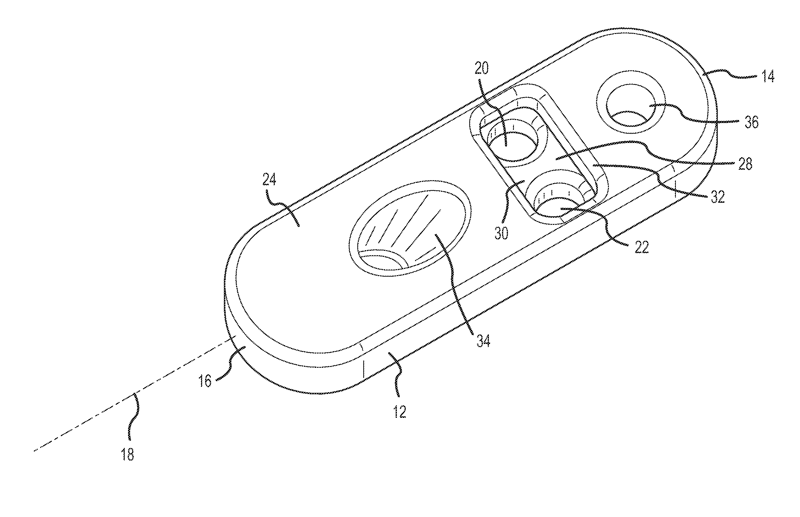
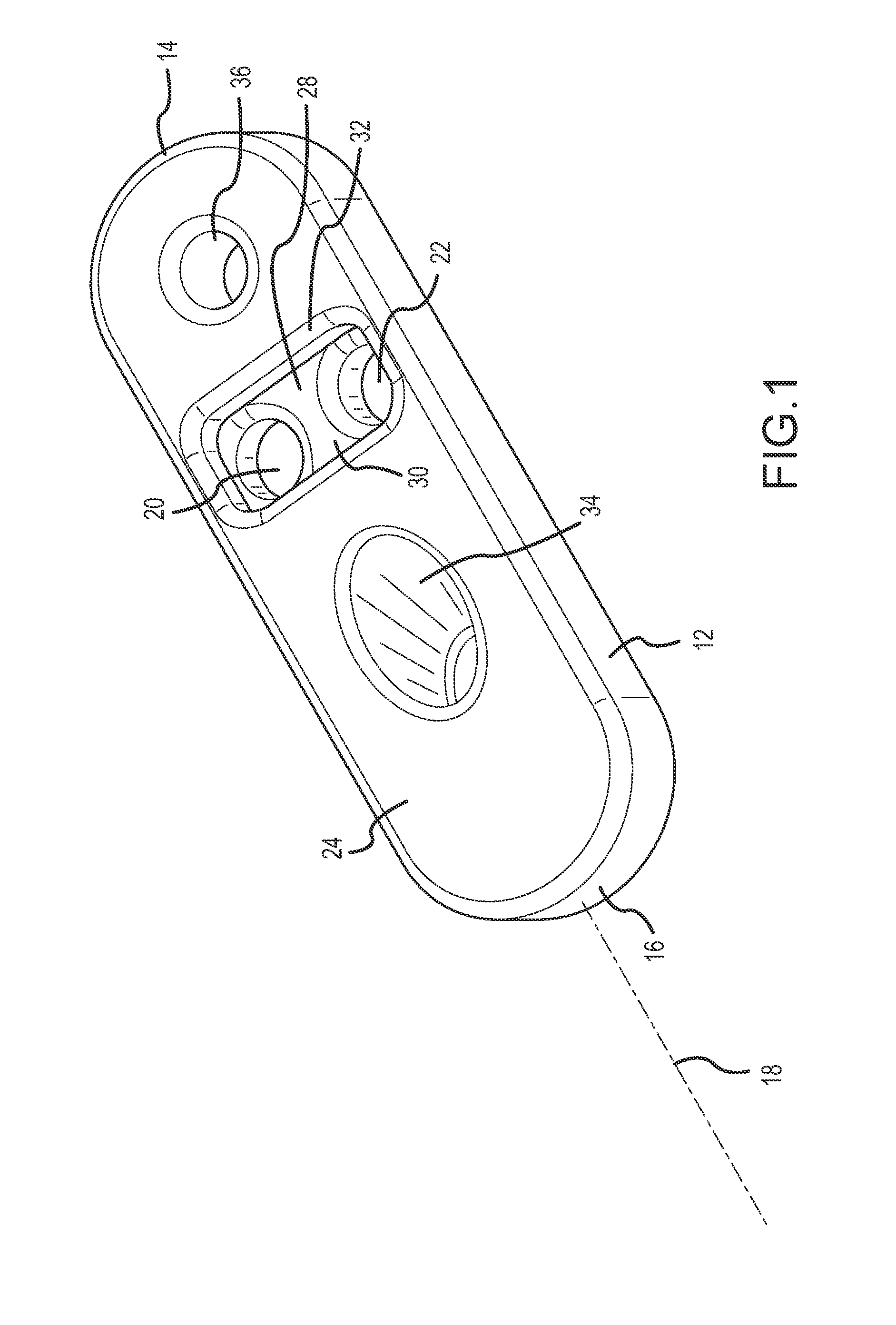
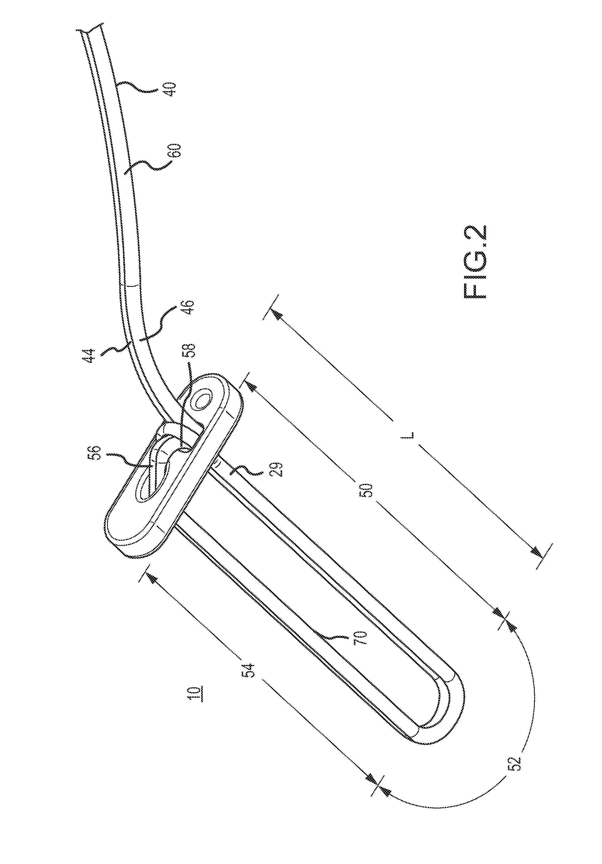
[0021]A suspensory graft fixation device 10 constructed in accordance with the principles of this invention is shown in the drawings. Device 10 comprises an elongated anchor member 12 and suture in the form of filamentous strand 40. Anchor member 12 has a first end 14, a second end 16, an axis 18, and a pair of suture receiving apertures 20 and 22. Anchor member 12 has a top surface 24 and a bottom surface 26 (best seen in FIG. 4). Bottom surface 26 is sometimes referred to as the proximal surface and is intended to be placed adjacent a bone tunnel exit. As used herein, the term “proximal” refers to the side of the bone containing the bone tunnel (i.e., extending inwardly away from the surface of the lateral femur in an ACL procedure), and the term “distal” refers to the side of the bone against which the transverse anchor member rests (i.e., extending outwardly away from the surface on the lateral femur). Apertures 20 and 22 are situated on opposite sides of a central bridge portio...


PUM


Abstract

A suspensory fixation device has an elongated anchor member adapted to be transversely situated at the exit of a bone tunnel. A graft supporting loop member formed of a pair of parallel suture limbs extending from a bight portion is suspended transversely from the anchor member and has a loop length which is adjustable so the graft ligament can be supported in the bone tunnel at varying distances from the anchor member. When a graft ligament is attached to the saddle end of the loop member, the length of the loop member may be shortened by simply pulling distally on the pair of limbs at one end of the loop member to pull the graft ligament into the bone tunnel a predetermined distance or until it bottoms out at the floor of the bone tunnel. When tension is applied to the loop member by the graft pulling the loop proximally, the bight portion of the suture automatically locks the graft supporting loop member in place.

Description

BACKGROUND OF THE INVENTION[0001]1. Field of the Invention[0002]This invention relates to surgical devices for the repair and reconstruction of soft tissue injuries. In particular, this invention relates to devices and methods for the surgical implantation of replacement (autograft or allograft or artificial) ligament grafts. Still more particularly, the invention relates to the surgical repair of anterior cruciate ligament grafts.[0003]2. Description of the Prior Art[0004]The repair and reconstruction of torn or damaged soft tissues is a common surgical procedure. For example, replacement graft ligaments may be secured at the site of the original ligament. The procedure generally involves drilling bone tunnels into adjacent bones at the site of the original ligament and securing a graft ligament within these bone tunnels. In many applications, such as in the knee joint, such procedures may be performed arthroscopically. The graft ligament may be an autograft, an allograft, a xenogr...

Claims


Application Information

Patent Timeline
IPC IPC(8): A61F2/08A61B17/04
CPCA61F2/0811A61B17/0401A61B2017/0459A61F2002/0882A61F2002/0817A61F2002/0852A61B2017/0404
Inventor KAM, ANDREW S.LOMBARDO, GIUSEPPEMILLER, PETER C.FITTS, STEVEN E.
Owner LINVATEC
Learn More