Artificial hip joint stem and artificial hip joint including the same

a hip joint and stem technology, applied in the field of artificial hip joint stems, can solve the problems of decreased bone density, increased surface roughness of stems, increased friction against bone, etc., and achieve excellent stem insertability and prevent the distal part of the stem

Active Publication Date: 2015-07-16
KYOCERA CORP
View PDF13 Cites 3 Cited by
  • Summary
  • Abstract
  • Description
  • Claims
  • Application Information

AI Technical Summary

Benefits of technology

[0010]The present invention produces the effects of exhibiting the excellent stem insertability and preventing the distal part of the stem from being fixed to the femoral bone.

Problems solved by technology

However, an increase in the surface roughness (Ra) of the stem increases friction against the bone.
Therefore, when inserting the stem, a distal part of the stem is easy to contact with soft tissue and the cancellous bone at the proximal part of the femoral bone, resulting in poor insertability of the stem.
Once the distal part of the stem is fixed to the femoral bone, there is possibility of occurrence of thigh pain and stress shielding in which bone density decreases and the bone shrinks due to less load applied to the bone.

Method used


Image

  • Artificial hip joint stem and artificial hip joint including the same
  • Artificial hip joint stem and artificial hip joint including the same
  • Artificial hip joint stem and artificial hip joint including the same

Examples


first embodiment

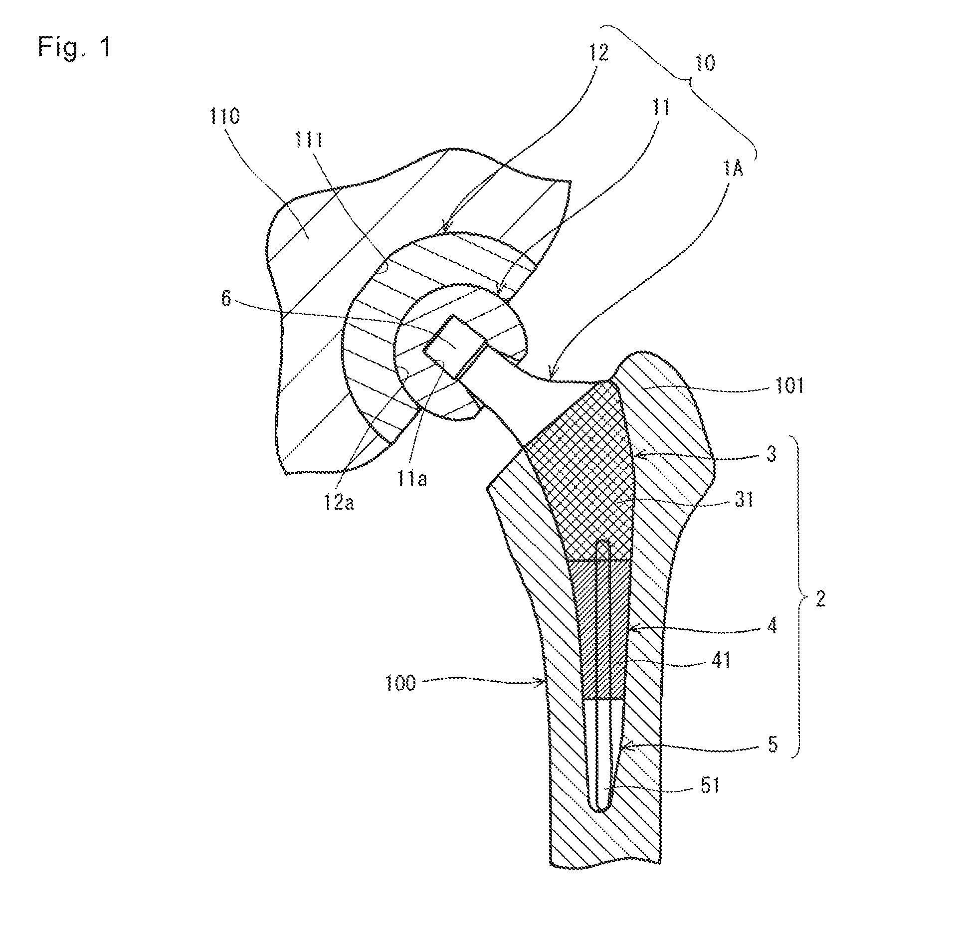
[0023]An artificial hip joint stem and an artificial hip joint according to a first embodiment of the present invention are described in details below with reference to FIGS. 1 to 4C. Although the following description is made taking as an example the case of implanting the stem in the left leg, the stem of the present invention can also be implanted in a right leg.

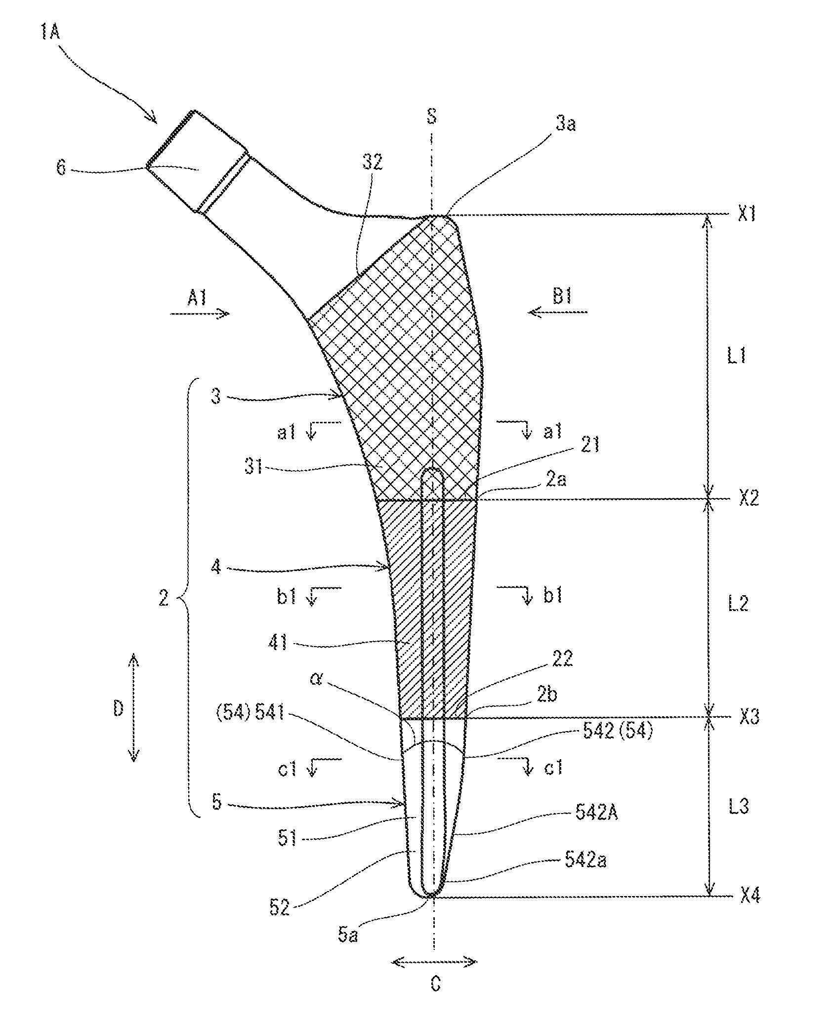
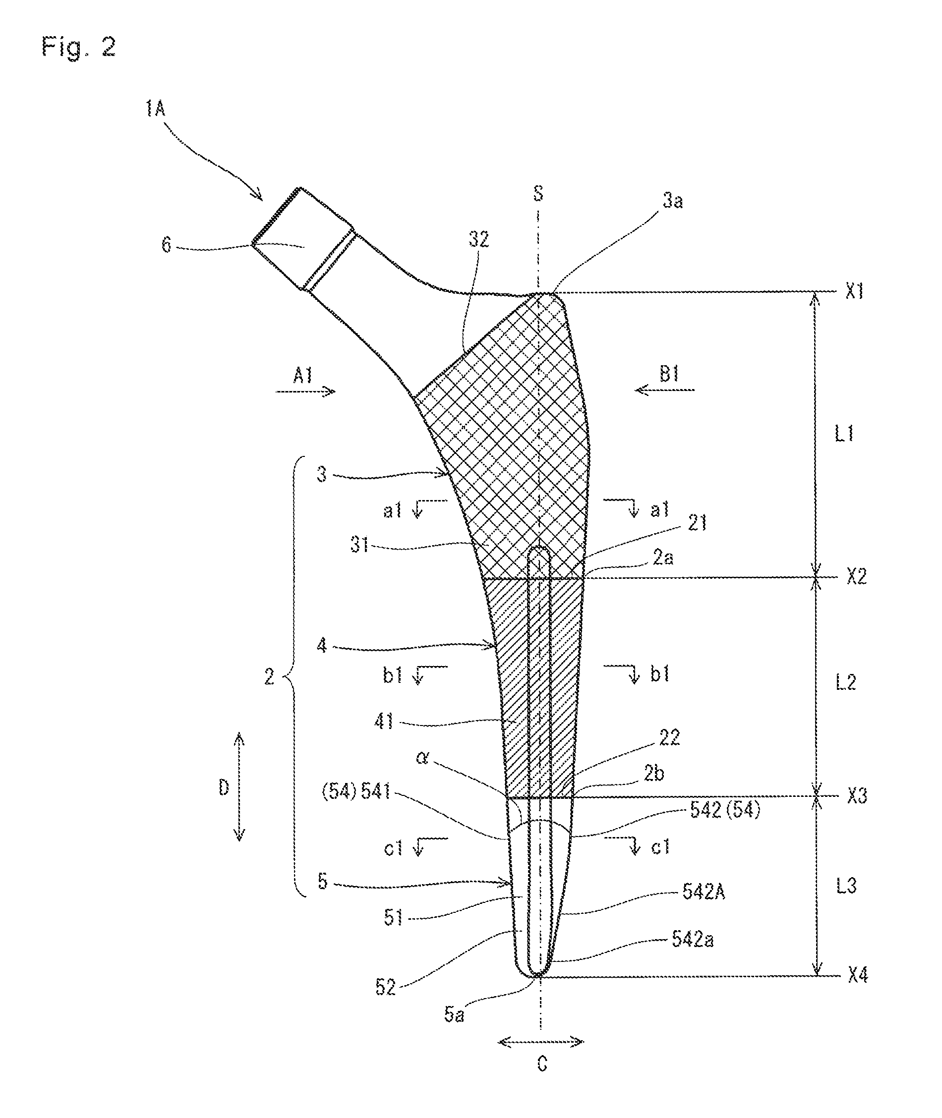
[0024]As shown in FIG. 1, the artificial hip joint stem 1A of the present embodiment is the substantially rod-shaped curved member and constitutes the artificial hip joint 10. The stem 1A includes a stem body 2. The stem body 2 of the present embodiment is divided into a stem proximal part 3 located at a proximal part, a stem distal part 5 located at a distal part, and a stem intermediate part 4 located between the stem proximal part 3 and the stem distal part 5.

[0025]The phrase “proximal part” denotes the part located more closer to the head of a human body than an object to compare upon implantation of the artificial hi...

second embodiment

[0050]A stem and an artificial hip joint according to a second embodiment of the present invention are described in details below with reference to FIGS. 5, 6A and 6B. In FIGS. 5, 6A and 6B, the same components as those in FIGS. 1 to 4C are identified by the same reference numerals and the description thereof is generally omitted.

[0051]The present embodiment differs from the foregoing first embodiment in configuration of a first boundary part 21 of a rough surface 31 and a smooth satin surface 41 as well as a second boundary part 22 of the smooth satin surface 41 and a shiny surface 51. Specifically, as shown in FIG. 5, both of the first boundary part 21 and the second boundary part 22 in the stem 1B of the present embodiment are respectively inclined counterclockwise around points 21c and 22c located on a central axis S with respect to a reference line substantially perpendicular to the central axis S, namely, straight lines X2 and X3 in a front view.

[0052]More specifically, the fi...

third embodiment

[0058]A stem and an artificial hip joint according to a third embodiment of the present invention are described in details below with reference to FIGS. 7 to 9C. In FIGS. 7 to 9C, the same components as those in FIGS. 1 to 6B are identified by the same reference numerals and the description thereof is generally omitted.

[0059]The present embodiment differs from the foregoing first embodiment in position of the shiny surface 51. Specifically, in the stem 1C of the present embodiment, the shiny surface 51 is located on an medial side surface 541 and an lateral side surface 542 of a stem distal part 5 as shown in FIGS. 7, 8A and 8B. Further in the stem 1C of the present embodiment, a smooth satin surface 41 extends from the stem intermediate part 4 to distal end portions 52a and 53a of a front surface 52 and a rear surface 53 of the stem distal part 5, respectively.

[0060]These configurations also produce effects similar to those of the stem 1A according to the foregoing first embodiment...


PUM


Abstract

An artificial hip joint stem of the present invention includes a stem body divided into a stem proximal part, a stem distal part, and a stem intermediate part located between the stem proximal part and the stem distal part. The stem body includes a rough surface located at the stem proximal part and having a surface roughness (Ra) of 10-80 μm, a smooth satin surface located at the stem intermediate part and having a surface roughness (Ra) of 0.1-1.0 μm, and a shiny surface located at the stem distal part and having a surface roughness (Ra) of less than 0.1 μm. The present invention also provides an artificial hip joint including the artificial hip joint stem.

Description

FIELD OF INVENTION[0001]The present invention relates to an artificial hip joint stem fixed to a femoral bone and an artificial hip joint including the artificial hip joint stem.BACKGROUND ART[0002]In order to restore the function of a hip joint deteriorated by disease or injury due to an accident or the like, hip replacement arthroplasty for replacing the hip joint with an artificial hip joint has been carried out conventionally. An artificial hip joint stem (hereinafter generally referred to as “stem”) among members constituting the artificial hip joint is the substantially rod-shaped curved member inserted and fixed to a proximal part of the femoral bone.[0003]The stem is classified into a stem using cement and a stem using no cement (hereinafter generally referred to as “cementless stem”) according to a method of fixing the stem to the femoral bone. As the cementless stem, a bone preservation type stem that reduces injury to the femoral bone and its surrounding tissues has recei...

Claims


Application Information

Patent Timeline
Patent Type & Authority Applications(United States)
IPC IPC(8): A61F2/36
CPCA61F2/3662A61F2/3609A61F2002/30321A61F2002/3611A61F2002/3686A61F2/30771A61F2/367A61F2/3672A61F2/3676A61F2002/30028A61F2002/3082A61F2002/30906
Inventor SLATER, NICHOLASMIYASHITA, TAKATOSHIKUROSHIMA, ATSUSHIFUJIMURA, SHION
Owner KYOCERA CORP
Why Eureka
Try Eureka