Method for controlling an electric generator

Active Publication Date: 2015-07-16
WOBBEN PROPERTIES GMBH
View PDF5 Cites 31 Cited by
  • Summary
  • Abstract
  • Description
  • Claims
  • Application Information

AI Technical Summary

Benefits of technology

The invention aims to solve the problem of a loss of stability in the power supply system that can cause damage. The solution proposes a method to minimize the risks associated with such a loss of stability.

Problems solved by technology

Therefore, such a fault is monitored, and if it is detected, an interruption of the feeding is triggered.
For example, the generator's operating point can suddenly and undesirably shift to an area that results in this specific generator becoming instable during the feeding into the respective grid connection point.

Method used


Image

  • Method for controlling an electric generator
  • Method for controlling an electric generator
  • Method for controlling an electric generator

Examples


Embodiment Construction

[0077]Below, identical reference signs for similar, but non-identical elements may be provided, or they can also be provided for elements that are only illustrated schematically or symbolically, and which may have different details, but which are not relevant for the respective explanation.

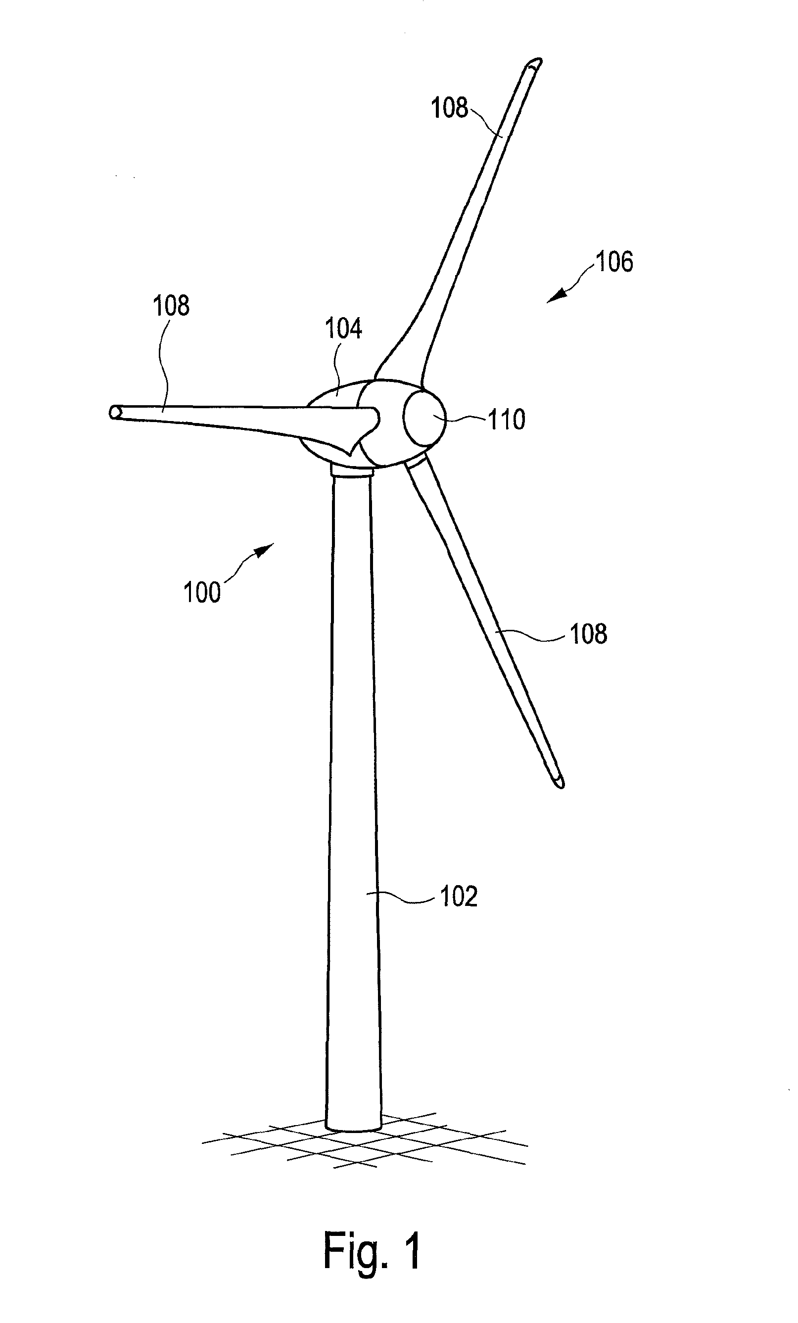
[0078]FIG. 1 shows wind power installation 100 with tower 102 and nacelle 104. Rotor 106 with three rotor blades 108 and spinner 110 is located on nacelle 104. Rotor 106 is set in operation by the wind in a rotating movement, thereby driving a generator in nacelle 104.

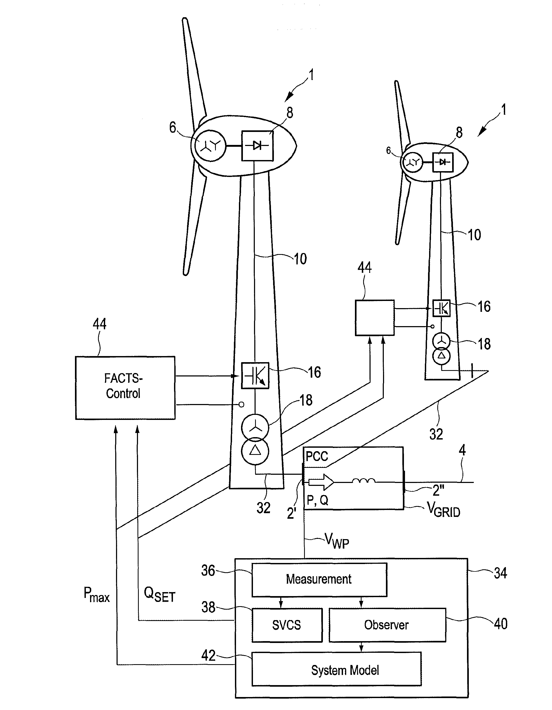
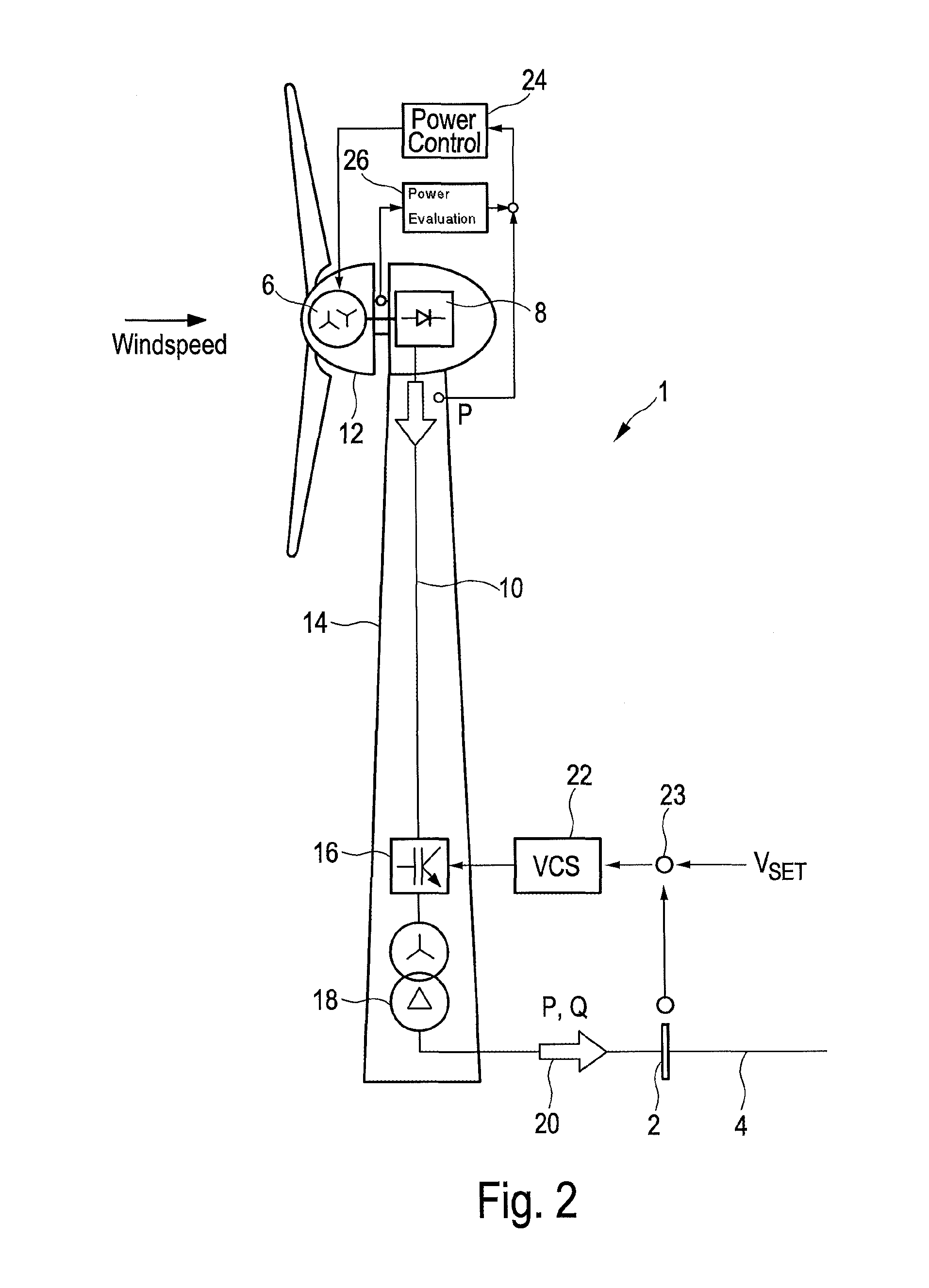
[0079]FIG. 2 shows a schematic view of a wind power installation 1 connected to electrical supply grid 4 over grid connection point 2. Electrical supply grid 4 is simply referred to as grid 4 or network 4, whereby these terms are used synonymously.

[0080]Wind power installation 1 comprises generator 6, which is driven by the wind, thereby producing electric energy. One of the embodiments of generator 6 is an electrically excited multi...


PUM


Abstract

The invention relates to a method for controlling a generator of electric energy that is connected to an electrical supply grid on a grid connection point, comprising the following steps: feeding electrical power into the electrical supply grid, whereby the generator is operated in a first operating point, interrupting the feeding so that no power is fed into the supply grid if a fault in the electrical supply grid or a fault of the feeding into the electrical supply grid exists or is displayed, resuming the feeding so that electrical power is again fed into the supply grid, whereby the generator resumes the feeding in a second operating point or is gradually increased in said second operating point, and the second operating point is designed in such a way that it feeds into the supply grid with a higher stability reserve than the first operating point.

Description

BACKGROUND [0001]1. Technical Field[0002]The present invention relates to a method for controlling a generator of electric energy that is connected to an electrical supply grid on a grid connection point. Furthermore, the present invention relates to a generator of electric energy that is connected to an electrical supply grid.[0003]2. Description of the Related Art[0004]Feeding electric energy into an electrical supply grid, such as the European grid or the US power grid, is generally known. The electrical supply grid as described below refers to the widely accepted AC voltage grid. This does not exclude the presence of DC voltage sections in the grid. Likewise, frequency-independent aspects may generally also refer to a DC voltage grid. Historically, energy is fed into an electrical supply grid with a large power station that drives a synchronous generator using primary energy, such as coal, nuclear energy or gas. Depending on the number of pole pairs and the speed of the synchron...

Claims


Application Information

Patent Timeline
IPC IPC(8): F03D7/04G05B15/02H02J3/00F03D9/00H02P9/10
CPCF03D7/048F03D9/005H02J2003/001H02J3/00G05B15/02H02P9/105H02J3/386F03D9/255F03D7/0284F03D7/04H02J3/16H02J3/24F03D9/257H02J2300/28H02J3/381Y02E10/76Y02E40/30Y02E10/72
Inventor DIEDRICHS, VOLKERBUSKER, KAIBEEKMANN, ALFRED
Owner WOBBEN PROPERTIES GMBH
Why Eureka
Try Eureka