Object fusion system of multiple radar imaging sensors

a technology of object fusion and radar imaging, applied in the direction of reradiation, measurement devices, instruments, etc., can solve the problems of difficult assessment of close-by-targets, sparse inputs from radars, etc., and achieve the effect of improving the tracking position of objects

Active Publication Date: 2015-07-16
GM GLOBAL TECH OPERATIONS LLC
View PDF0 Cites 71 Cited by
  • Summary
  • Abstract
  • Description
  • Claims
  • Application Information

AI Technical Summary

Benefits of technology

[0003]An advantage of an embodiment is the enhanced tracking of an objects position and orientation relative to a host vehicle. The host vehicle utilizes Doppler measurement data to determine which portions of the radar data form a cluster as well as determining whether the cluster is stationary or dynamic. Tracking a position and the shape of the object allows the host vehicle to determine the orientation of the object during each time frame. Since an objects shape will change as seen by host vehicle, based on the changes of the shape, the orientation may be determined at each instance of time and tracked accordingly. As a result, the respective tracking system may communicate the remote vehicle orientation, position, and speed to other vehicle subsystems for their use with objects exterior of the vehicle.

Problems solved by technology

However, inputs from radars are often sparse tracked targets.
Moreover, radar systems are often predicated on assuming the target is a single point which makes it even more difficult to assess for close-by-targets.

Method used


Image

  • Object fusion system of multiple radar imaging sensors
  • Object fusion system of multiple radar imaging sensors
  • Object fusion system of multiple radar imaging sensors

Examples


Embodiment Construction

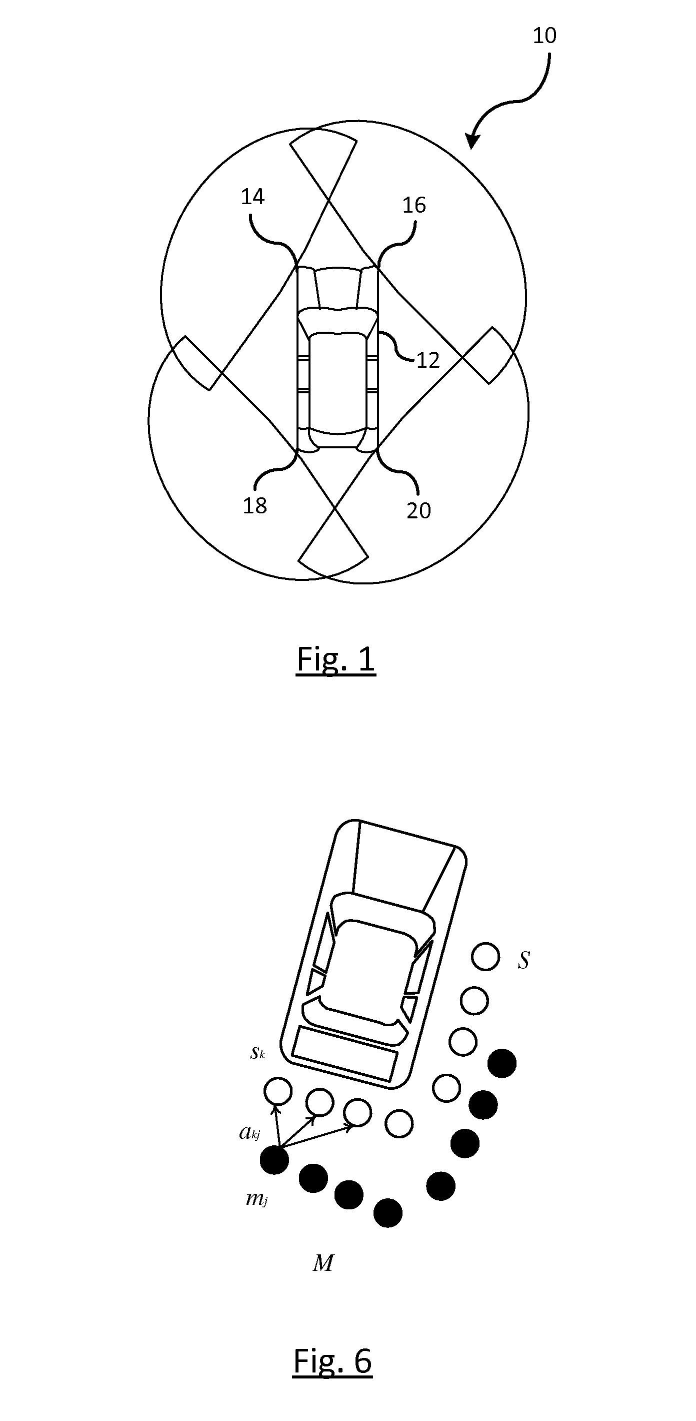
[0017]FIG. 1 illustrates a vehicle surround sensing system 10 for detecting objects 360 degrees around a vehicle 12. The system 10 includes a first sensing device 14, a second sensing device 16, a third sensing device 18, and a fourth sensing device 20. Each of the sensors detects objects within a sensed region surrounding the vehicle 12. The data from each of the sensors are fused to cooperatively track objects exterior of the vehicle 12. It should be understood that the number of sensors as shown in FIG. 1 is exemplary, and either one or a plurality of sensors may be used without deviating from the scope of the invention.

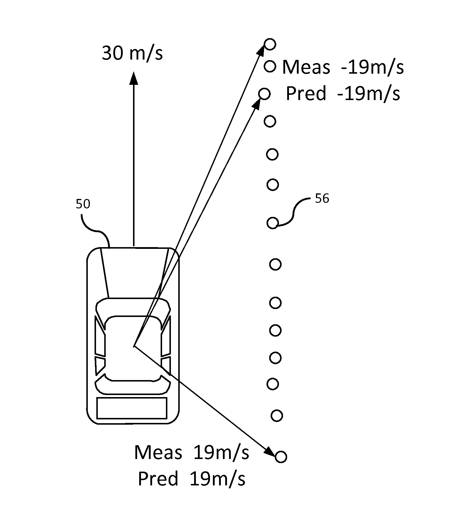
[0018]Short range radar sensors are traditionally narrow band and have issues when sensing objects that represent a dense scene or close-by extended objects to lack of range. For example, for a host vehicle driving down a highway with a remote vehicle on one side of the host vehicle and a guard rail on the other side of the vehicle, such objects are difficult to d...


PUM


Abstract

A method of detecting and tracking objects using multiple radar sensors. Objects relative to a host vehicle are detected from radar data generated by a sensing device. The radar data includes Doppler measurement data. Clusters are formed, by a processor, as a function of the radar data. Each cluster represents a respective object. Each respective object is classified, by the processor, as stationary or non-stationary based on the Doppler measurement data of each object and a vehicle speed of the host vehicle. Target tracking is applied, by the processor, on an object using Doppler measurement data over time in response to the object classified as a non-stationary object; otherwise, updating an occupancy grid in response to classifying the object as a stationary object.

Description

BACKGROUND OF INVENTION[0001]An embodiment relates to object sensor fusion.[0002]Radar systems are used to detect objects within the road of travel. Such systems utilize continuous or periodic tracking of objects over time to determine various parameters of an object. Often times, data such as object location, range, and range rate are computed using the data from radar systems. However, inputs from radars are often sparse tracked targets. Moreover, radar systems are often predicated on assuming the target is a single point which makes it even more difficult to assess for close-by-targets.SUMMARY OF INVENTION[0003]An advantage of an embodiment is the enhanced tracking of an objects position and orientation relative to a host vehicle. The host vehicle utilizes Doppler measurement data to determine which portions of the radar data form a cluster as well as determining whether the cluster is stationary or dynamic. Tracking a position and the shape of the object allows the host vehicle ...

Claims


Application Information

Patent Timeline
Patent Type & Authority Applications(United States)
IPC IPC(8): G01S13/66G01S13/931
CPCG01S13/66G01S7/415G01S13/72G01S13/726G01S13/878G01S13/9029G01S13/931G01S2013/93272G01S2013/93271
Inventor ZENG, SHUQINGSALINGER, JEREMY A.LITKOUHI, BAKHTIAR B.O'DEA, KEVIN A.PAZHAYAMPALLIL, JOELMURAD, MOHANNADNICKOLAOU, JAMES N.
Owner GM GLOBAL TECH OPERATIONS LLC
Why Eureka
Try Eureka