Systems, devices, methods and graphical user interface for configuring a building automation system

Inactive Publication Date: 2015-07-16
GREEN EDGE TECH
View PDF4 Cites 96 Cited by
  • Summary
  • Abstract
  • Description
  • Claims
  • Application Information

AI Technical Summary

Benefits of technology

[0005]The present disclosure is generally directed toward improving functionality of an automation system by enabling setup of the system during installation and configuration. In one embodiment, a method for configuring a building automation system is disclosed. In some embodiments, the method may include: obtaining a parameter for a building in which an automation system is to be installed within the building; receiving input for configuring a first component of the automation system and a second component of the automation system being installed, the input including a first location for installing the first component and a second location for installing the second component within the building; identifying each of the first and second components of the automation system bas

Problems solved by technology

However, conventional solutions for installing and configuring building automation systems for commercial or residential buildings fail to provide an efficient way for builders or their affilia

Method used


Image

  • Systems, devices, methods and graphical user interface for configuring a building automation system
  • Systems, devices, methods and graphical user interface for configuring a building automation system
  • Systems, devices, methods and graphical user interface for configuring a building automation system

Examples


Embodiment Construction

[0034]Reference now will be made in detail to embodiments of the present disclosure, examples of which are illustrated in the accompanying drawings. Wherever possible, the same reference numbers will be used throughout the drawings to refer to the same or like parts and / or components.

Overview

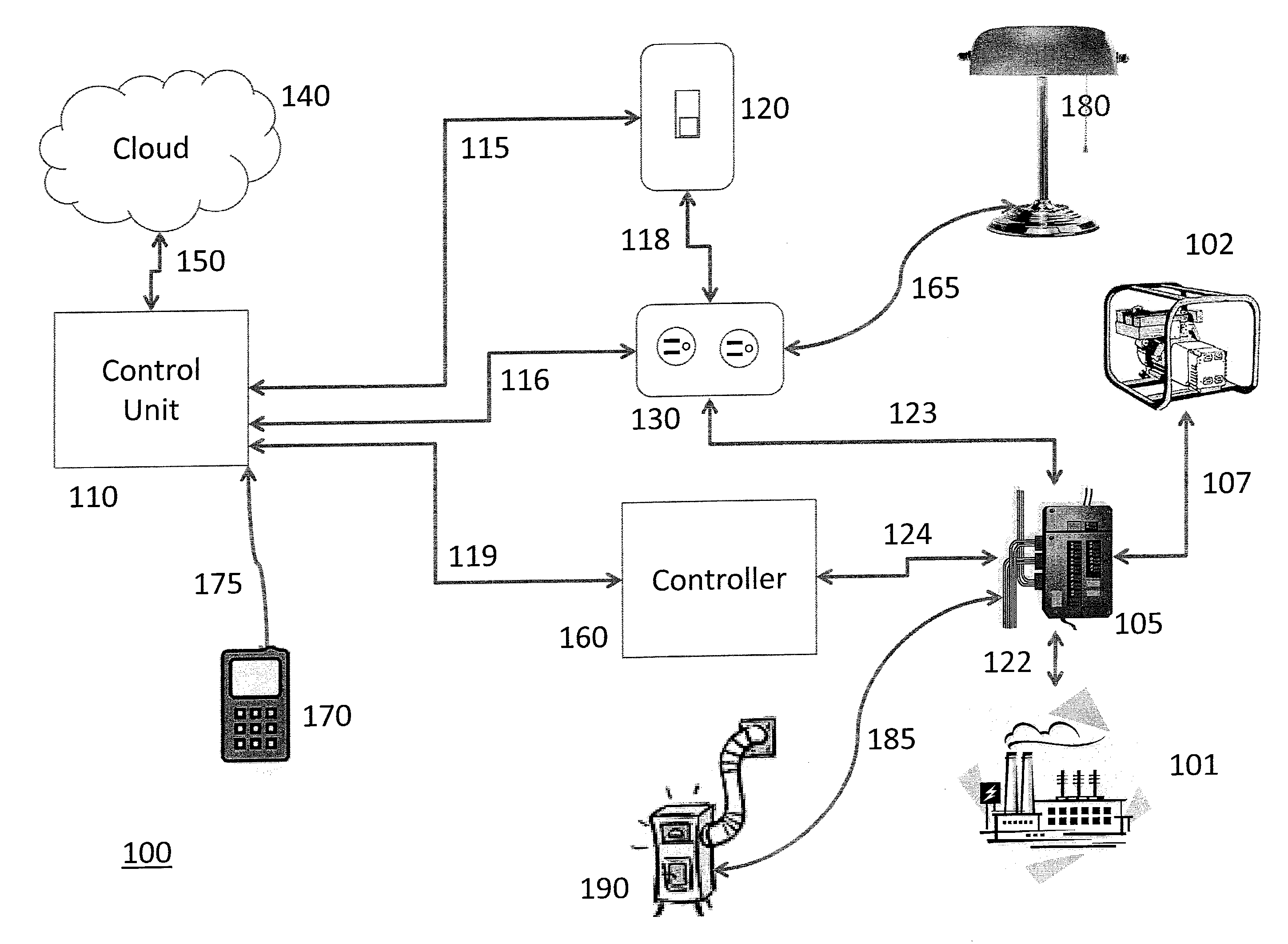
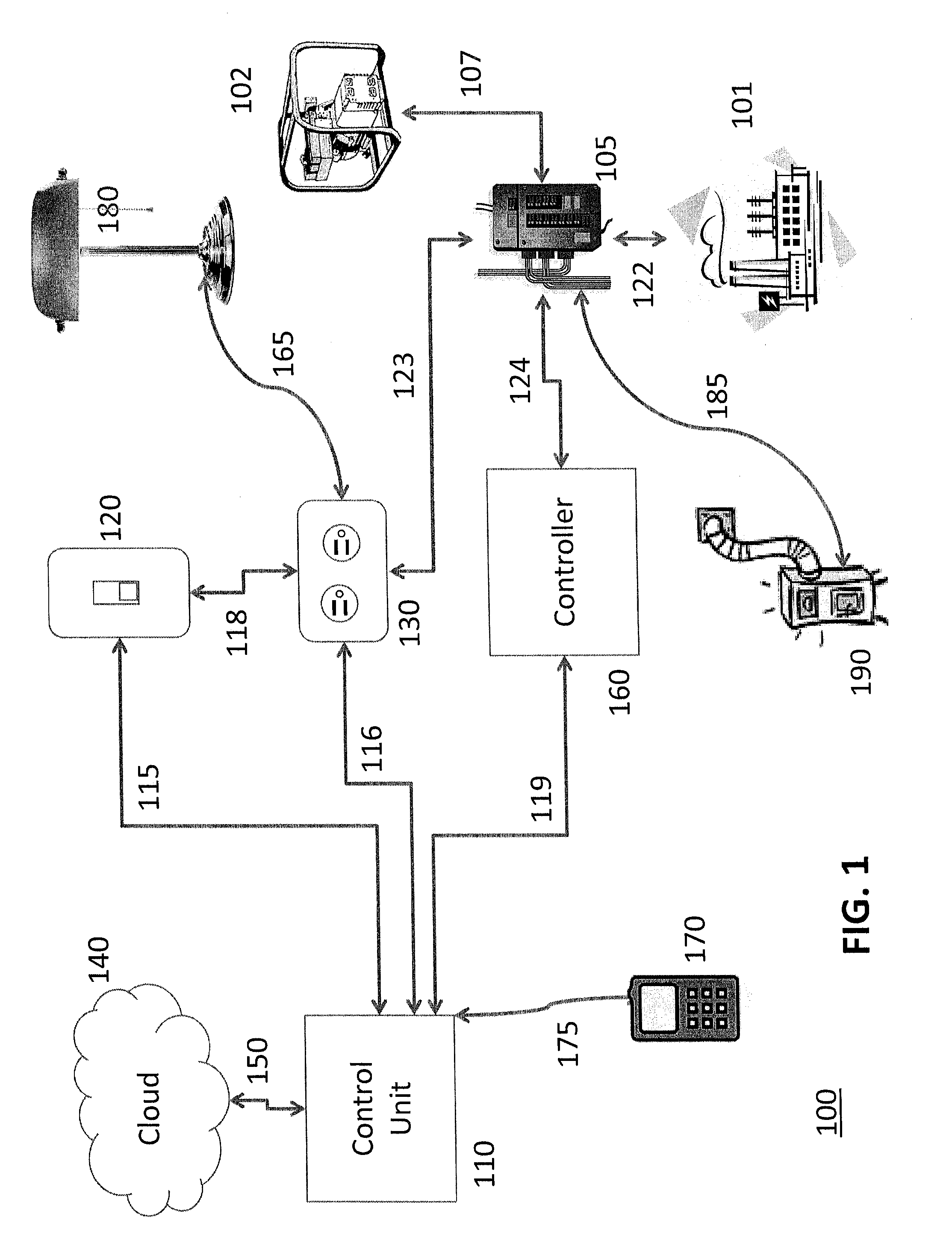
[0035]An automation system, e.g., a home automation system, generally may include one or more switches and one or more outlets (or other suitable power delivery components), with the user desiring to control which outlet or outlets are controlled by each of the switch(es). Existing X10 devices require the user to manually set an address on the switch(es) and the outlet(s), wherein an outlet would respond to a switch with an identical address, e.g., the identically addressed switch may enable and / or disable power supplied by the outlet on command.

[0036]Embodiments of the present disclosure may include, among other things, an automation system. Examples of suitable systems include those described ...


PUM


Abstract

Systems and methods are provided for configuring an automation system. A parameter for a building in which an automation system is to be installed is obtained. Configuration information is obtained for properly configuring components of the automation system in accordance with a parameter for the building. It is determined whether or not each of the components of the automation system being installed within the building is properly configured based on the obtained configuration information and input received from a user indicating the locations of the respective components within the building. A notification is provided to the user, which indicates the results of the determination for one or more of the components, and the user is presented with options for modifying configuration settings for one or more of the components.

Description

FIELD OF THE INVENTION[0001]Embodiments of the present disclosure are generally directed to systems, devices, and methods for configuring a building automation system. More particularly, embodiments of the present disclosure are directed to systems, devices, and methods for configuring newly installed components of a building automation system.BACKGROUND OF THE INVENTION[0002]Many components of a building automation system may be deployed and installed at the construction site during the initial construction of a building (e.g., a home or other type of residential or nonresidential structure). For example, the installation process for a home automation system generally involves the collection of serial numbers or other unique identification information for each home automation device or component to be installed. Other information that may be collected includes the location and function of the devices to be installed within the building. Once installed, the devices also will need to...

Claims


Application Information

Patent Timeline
IPC IPC(8): G05B15/02H04L12/28
CPCH04L12/2803G05B15/02B25J9/1689G05B2219/2642
Inventor STEELE, SCOTT A.ALBERTH, JR., WILLIAM P.CAMPBELL, JOSHUA E.CAMPBELL, JODY L.RICE, WILLIAM D.HARTSFIELD, DAVID K.
Owner GREEN EDGE TECH
Why Eureka
Try Eureka