Image processing device, imaging device, computer, image processing method and computer readable non-transitory medium

Active Publication Date: 2015-07-16
FUJIFILM CORP
View PDF5 Cites 11 Cited by
  • Summary
  • Abstract
  • Description
  • Claims
  • Application Information

AI Technical Summary

Benefits of technology

The present invention aims to provide a technology that can reduce the amount of data stored in the restoration filter used in point image restoration processing while maintaining the accuracy of the restoration. The invention achieves this by obtaining filter information based on statistical information related to point image restoration and the optical information indicating the point image intensity distribution, and calculating the filter coefficient with this information as a constraint condition. By determining the information amount required for storing the filter coefficient based on the characteristics of the point image intensity distribution, the invention can design the restoration filter of the best characteristic with a reduced data storage amount. This reduces the computation amount for filter design and also facilitates the determination of the filter information amount by utilizing compressed information associated with the point image intensity distribution. Overall, the invention enables efficient use of data storage space in point image restoration processing.

Problems solved by technology

As described above, while a huge amount of storage data is required in order to appropriately perform the point image restoration processing utilizing a restoration filter, reduction of a storage data amount is one of big problems.
However, since the restoration filter is configured by many taps and a filter coefficient is allocated to each tap, the storage loads are extremely large.
In the apparatuses disclosed in Japanese patent application publication No. 2003-172873 and Japanese patent application publication No. 2012-129932, no device to effectively reduce the data amount of the restoration filter of the point image restoration processing while maintaining point image restoration accuracy is employed in particular.
Also, while Japanese patent application publication No. 2012-073691 discloses a technology of reducing a storage amount of data required for reconfiguration of the optical transfer function of the imaging optical system, no device to directly reduce the storage data amount of the restoration filter for the point image restoration processing is disclosed or suggested.
That is, the technology disclosed in Japanese patent application publication No. 2012-073691 is for reducing an information amount of the optical transfer function for preparing an image recovery filter, but is not for reducing the storage amount of the prepared image recovery filter itself.

Method used


Image

  • Image processing device, imaging device, computer, image processing method and computer readable non-transitory medium
  • Image processing device, imaging device, computer, image processing method and computer readable non-transitory medium
  • Image processing device, imaging device, computer, image processing method and computer readable non-transitory medium

Examples


first embodiment

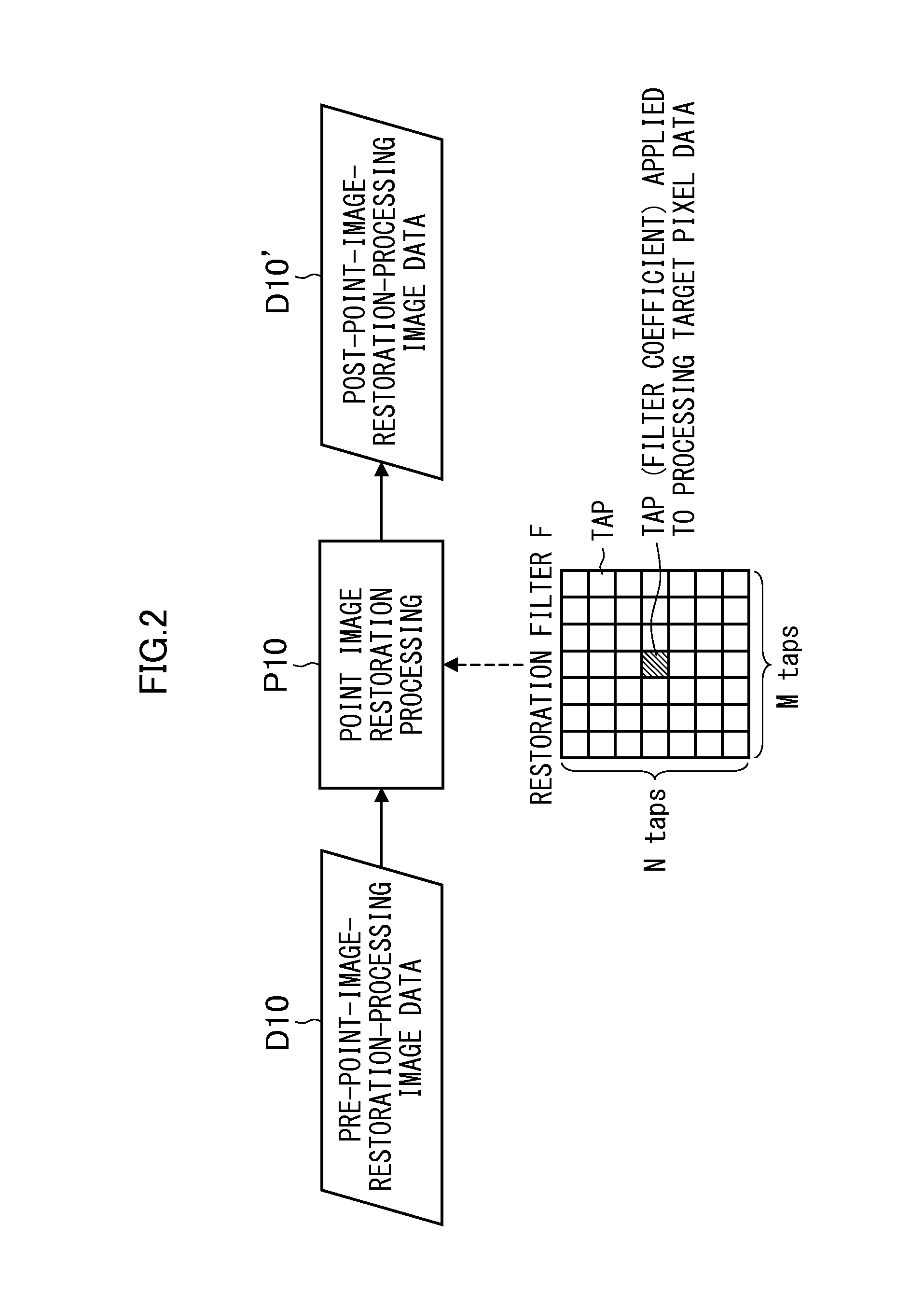
[0071]Generally, a restoration filter size of the point image restoration processing is correlated with a size of the PSF, and it is desirable to perform the point image restoration processing by the restoration filter with the larger number of taps for the PSF of larger point spread. Also, when the PSF is a symmetrical form, the restoration filter also becomes the symmetrical form and therefore an information amount of the restoration filter can be compressed by utilizing such symmetry. That is, by designing the restoration filter in consideration of “a feature (symmetry) of optical information (PSF or the like) indicating a point image intensity distribution of an optical system” and “another characteristic (the number of taps) for filter information compression” as constraint conditions, information required for the restoration filter can be efficiently compressed without lowering accuracy of the point image restoration processing.

[0072]FIG. 3 is a block diagram illustrating a me...

second embodiment

[0118]In the present embodiment, the same signs are attached for configurations in common with the first embodiment described above, and detailed descriptions thereof are omitted.

[0119]The optical transfer function (the optical information indicating the point image intensity distribution of the optical system used when acquiring image data) stored in the PSF storage unit 36 (see FIG. 4) can be stored in an arbitrary format. Below, a case of storing the optical transfer function (PSF) in the PSF storage unit 36 in a state that redundancy based on the symmetry is eliminated will be described.

[0120]The optical information stored in the PSF storage unit 36 in the present embodiment includes the data indicating the kind of the symmetry of the point image intensity distribution based on the PSF, and the data (compressed data) of the PSF compressed so as to reproduce the point image intensity distribution on the basis of the kind of the symmetry of the point image intensity distribution. ...

third embodiment

[0135]In the present embodiment, the same signs are attached for configurations in common with the first embodiment and the second embodiment, and detailed descriptions thereof are omitted.

[0136]The filter coefficient-format storage unit 42 (see FIG. 4) can store the filter coefficient D18, the filter information D16 and the PSF condition in an arbitrary format.

[0137]FIG. 8 is a functional block diagram illustrating the filter coefficient-format storage unit 42 according to the third embodiment.

[0138]The filter coefficient outputted from the filter coefficient calculating unit 40 in a format-specified and compressed form is recorded in the filter coefficient-format storage unit 42 together with the filter information (e.g. filter information ID (identifier p) and filter size data (M)). A reason for recording these pieces of information in the storage is that it is preferable to preserve the filter coefficient that is once calculated so as to be used immediately next time since it ta...


PUM


Abstract

An image processing device includes a statistical information acquiring unit, an optical information acquiring unit, a filter information calculating unit and a filter coefficient calculating unit. The filter information calculating unit obtains filter information of a restoration filter for point image restoration processing according to at least one of statistical information and optical information. The filter information includes information related to number of taps of the restoration filter and information indicating a kind of symmetry of the restoration filter. The filter coefficient calculating unit calculates a filter coefficient of the restoration filter according to the statistical information and the optical information with at least the information related to the number of taps of the restoration filter and the information indicating the kind of the symmetry of the restoration filter of the filter information as a constraint condition.

Description

CROSS-REFERENCE TO RELATED APPLICATIONS[0001]This application is a Continuation of PCT International Application No. PCT / JP2013 / 062001 filed on Apr. 24, 2013, which claims priority under 35 U.S.C. §119(a) to Japanese Patent Application No. 2012-212243 filed on Sep. 26, 2012 and Japanese Patent Application No. 2013-040681 filed on Mar. 1, 2013. Each of the above applications is hereby expressly incorporated by reference, in their entirety, into the present application.BACKGROUND OF THE INVENTION[0002]1. Field of the Invention[0003]The present invention relates to an image processing device, an imaging device, a computer, an image processing method and a computer readable non-transitory medium, and in particular, relates to a restoration filter used in point image restoration processing.[0004]2. Description of the Related Art[0005]In a subject image photographed through an imaging optical system, a so-called point spread phenomenon that a point subject has a minute spread is sometimes...

Claims


Application Information

Patent Timeline
IPC IPC(8): G06T5/00G06T5/10
CPCG06T5/10G06T5/001H04N23/81H04N23/663G06T5/73G06T5/00
Inventor NARUSE, YOUSUKEHAYASHI, KENKICHIENDO, HIROSHIIRIE, KOUSUKE
Owner FUJIFILM CORP
Why Eureka
Try Eureka