
Broadband Antenna

Active Publication Date: 2015-07-16
WISTRON NEWEB
View PDF5 Cites 12 Cited by
  • Summary
  • Abstract
  • Description
  • Claims
  • Application Information

AI Technical Summary

Benefits of technology

The present invention is about a new kind of antenna that can work over a wider range of frequencies and reduce its size. It includes a grounding unit, two radiating elements, a signal feed-in element, and a passive component made of an inductor. This new antenna design helps to match the impedance of the device and create a loop antenna effect, which increases the bandwidth of the antenna. The technical effect is a broadband antenna that is compact, efficient, and can work over a wide range of frequencies.

Problems solved by technology

A planar inverted-F antenna has conductive pins which can assist with impedance matching; however, this kind of antenna generally occupies larger space for achieving broadband and high radiation efficiency.
A coupled type antenna is generally smaller in size, but its performance can be vulnerable to environment fluctuations and it is hard to design for good impedance matching.
However, it is quite challenging to design a non-stereo type antenna with good radiation efficiency.
Since reducing external interference to the wireless communication device (i.e. reducing the SAR value) usually comes with the side effect of an impact on radiation efficiency, it is not easy to design an antenna with good radiation efficiency while the antenna also passes the qualification on its SAR.

Method used


Image

  • Broadband Antenna
  • Broadband Antenna
  • Broadband Antenna

Examples


Embodiment Construction

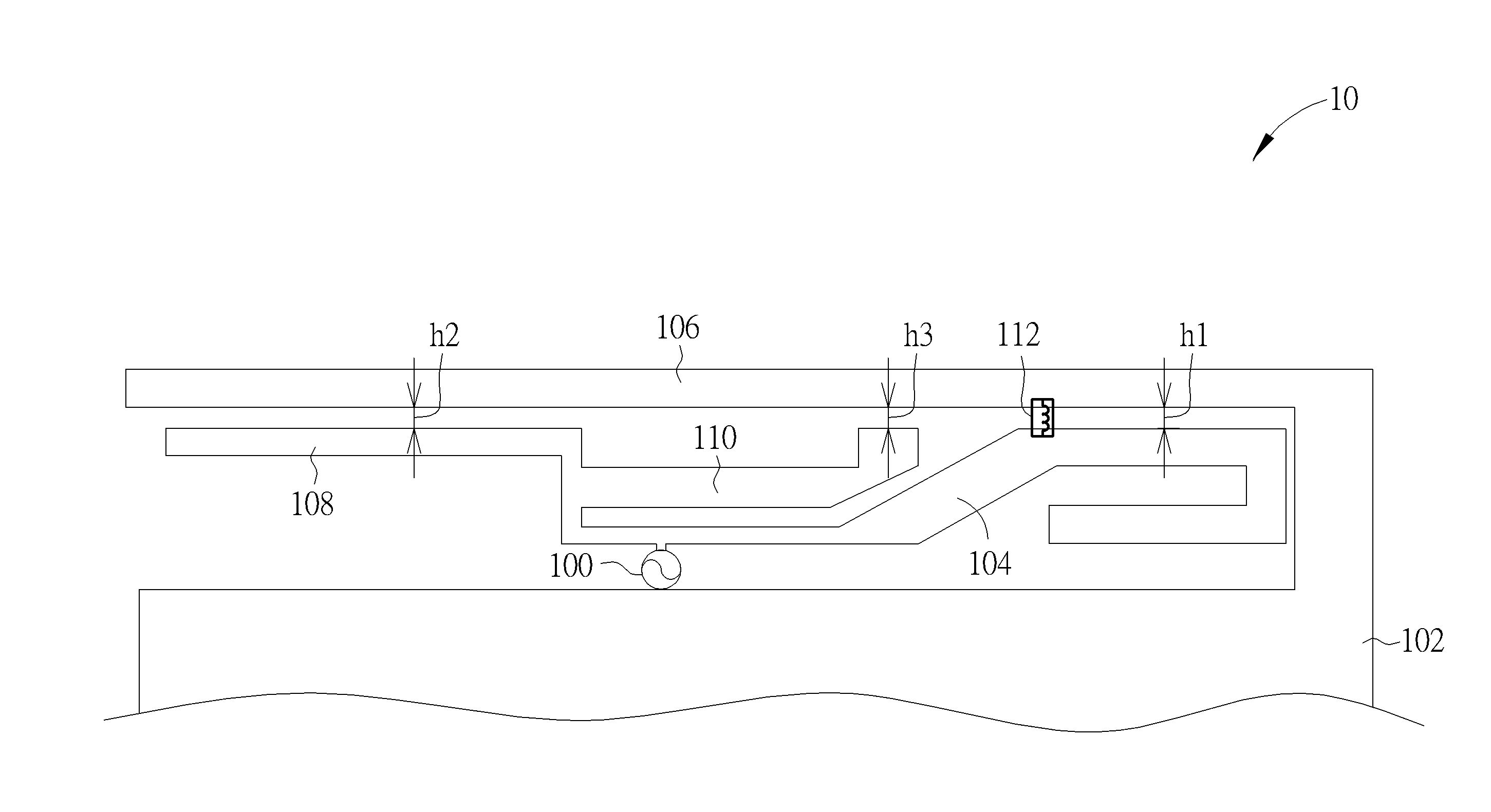
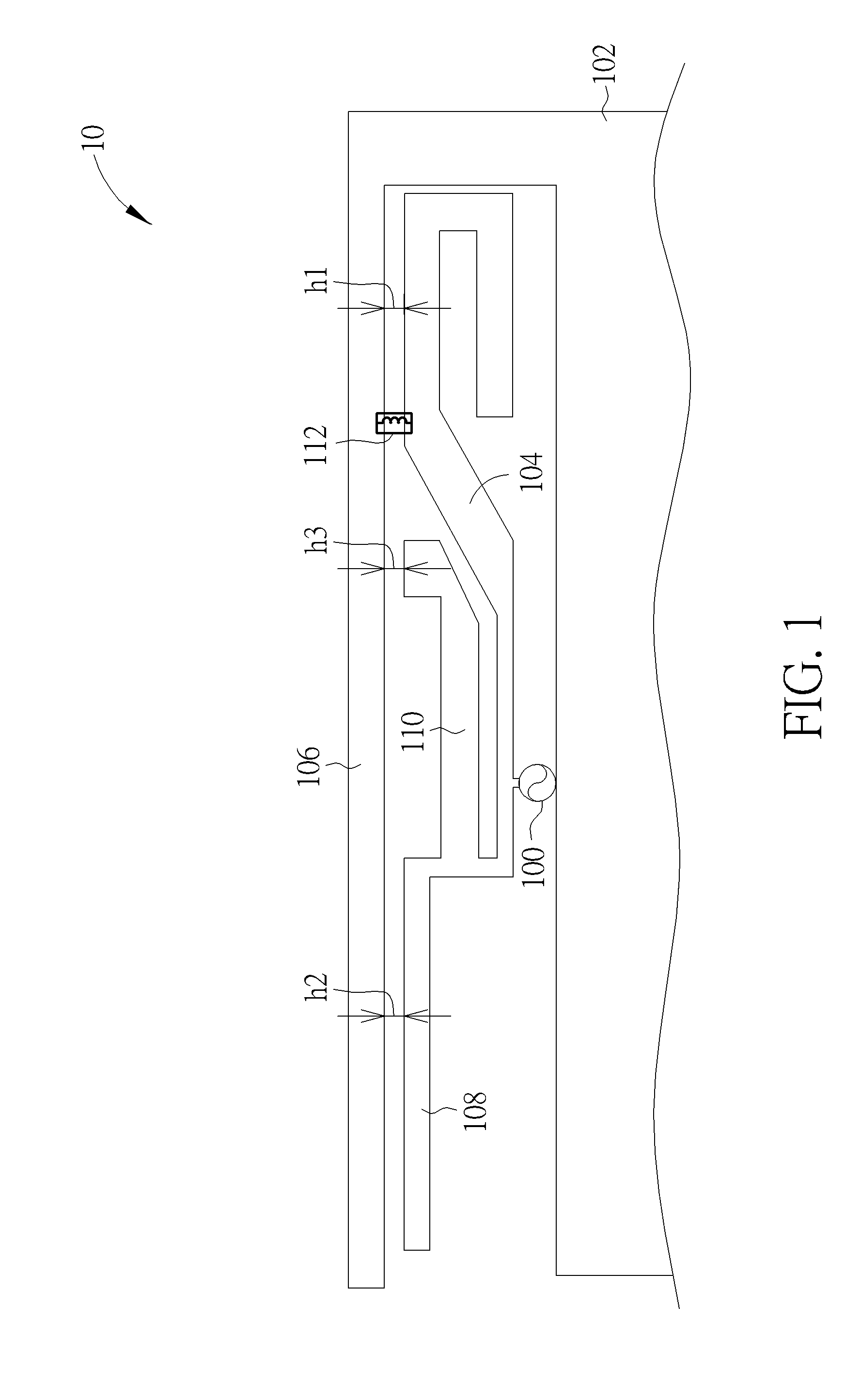
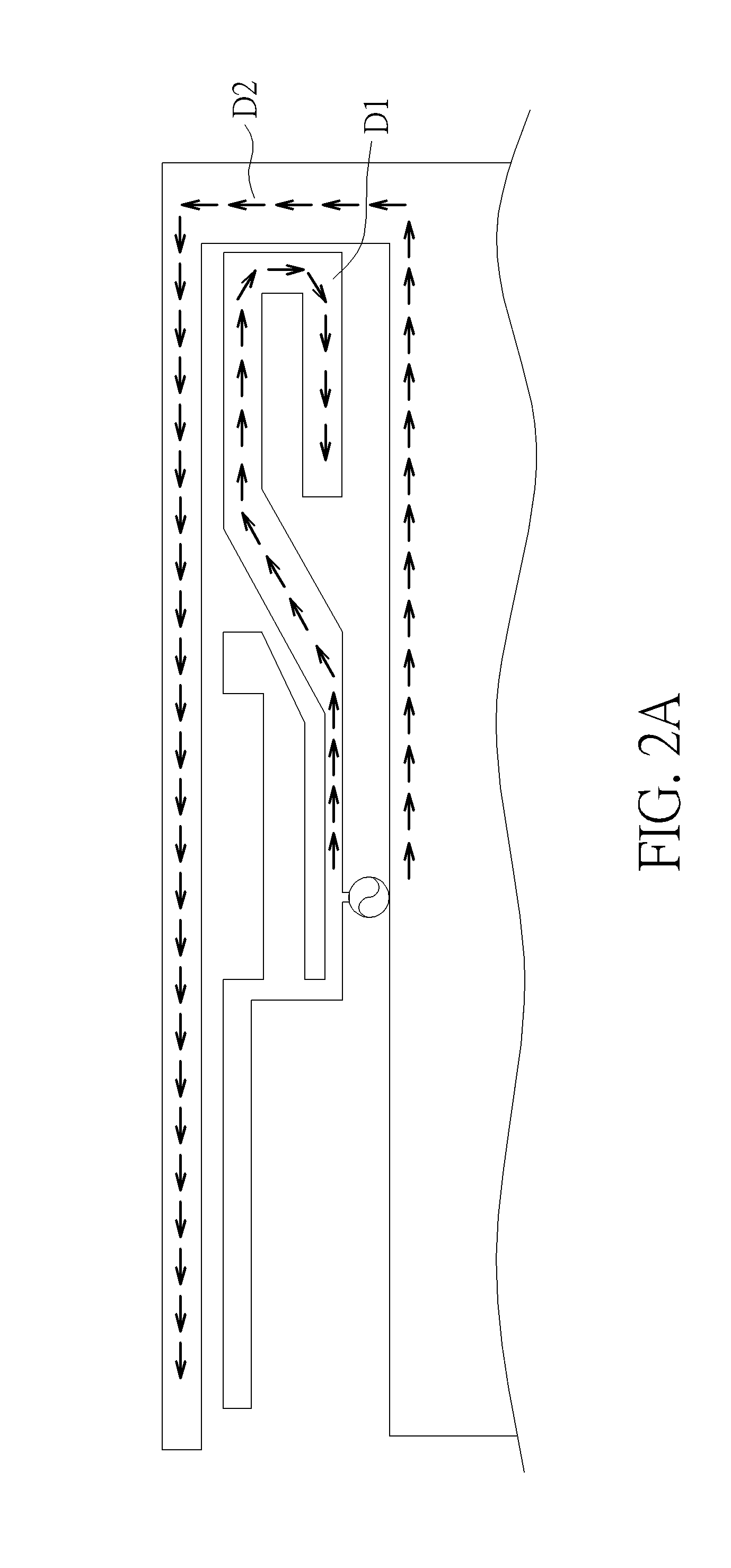
[0022]FIG. 1 shows a schematic diagram of a broadband antenna 10 according to an embodiment of the present invention. The broadband antenna 10 may be used in a wireless communication device for transmitting or receiving radio signals of a wide frequency band or multiple frequency bands, such as signals of a Long Term Evolution (LTE) wireless communication system, where its operational frequency bands are located approximately at 704 MHz-960 MHz and 1710 MHz-2700 MHz. The broadband antenna 10 includes a signal feed-in element 100, a grounding unit 102, a first radiating element 104, a second radiating element 106, and an inductor 112. The first radiating element 104 may be connected to a metal part. The metal part may include a third radiating element 108 and a fourth radiating element 110. The grounding unit 102 is used for providing ground. A ground terminal of the signal feed-in element 100 may be connected to a system grounding unit of the wireless communication device or the gro...


PUM


Abstract

A broadband antenna for a wireless communication device includes a grounding unit for grounding; a first radiating element; a second radiating element electrically connected to the grounding unit; a signal feed-in element for transmitting a radio signal to the first radiating element in order to emit the radio signal via the first radiating element; and a passive component comprising an inductor, where the passive component is electrically connected between the first and the second radiating elements to work in conjunction with the first radiating element, the second radiating element and the grounding unit to form a loop antenna effect.

Description

BACKGROUND OF THE INVENTION[0001]1. Field of the Invention[0002]The present invention relates to a broadband antenna, and more particularly, to a broadband antenna which comprises an inductor for increasing the antenna bandwidth, adjusting the impedance matching, and reducing the antenna dimensions.[0003]2. Description of the Prior Art[0004]Electronic products with wireless communication functionalities, such as laptops, tablet PCs, personal digital assistants (PDAs), mobile phones, wireless base stations, smart meters, and USB dongles, utilize antennas to send and receive wireless signals so as to access wireless networks. With the rise of the Long Term Evolution (LTE) technology, there has been a significant increase in demand for broadband antennas, as broadband antennas may improve the transmission rate of wireless communication products. On the other hand, it is also required that the antenna size should be as small as possible in order to meet demand for smaller and lighter pr...

Claims


Application Information

Patent Timeline
IPC IPC(8): H01Q5/00H01Q7/00
CPCH01Q5/0034H01Q7/005H01Q7/00H01Q5/321H01Q5/371H01Q5/378H01Q9/42
Inventor YOU, SHANG-SIANHUANG, CHIEN-TING
Owner WISTRON NEWEB
Learn More