Clock gating circuit for reducing dynamic power

a clock-gating circuit and dynamic power technology, applied in logic circuits, power consumption reduction, pulse techniques, etc., can solve the problems of dynamic power consumption and many conventional clock-gating circuits consuming an undesirable amount of dynamic power

Active Publication Date: 2015-07-16
QUALCOMM INC
View PDF2 Cites 29 Cited by
  • Summary
  • Abstract
  • Description
  • Claims
  • Application Information

AI Technical Summary

Problems solved by technology

Dynamic power consumption is an ongoing concern for integrated circuit (IC) devices, especially with the ever-increasing clock frequencies used in synchronous IC devices.
Unfortunately, many conventional clock-gating circuits consume an undesirable amount of dynamic power, even when disabled.

Method used


Image

  • Clock gating circuit for reducing dynamic power
  • Clock gating circuit for reducing dynamic power
  • Clock gating circuit for reducing dynamic power

Examples


Embodiment Construction

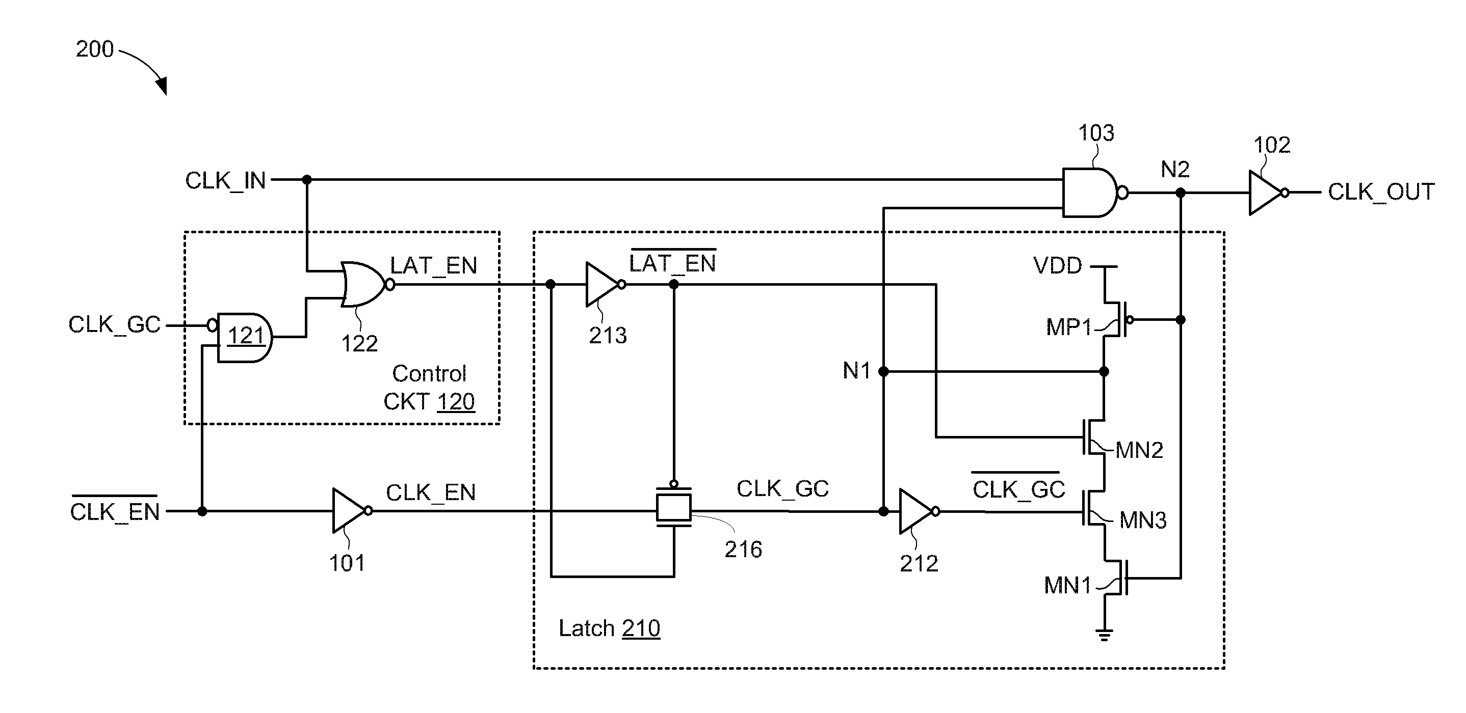
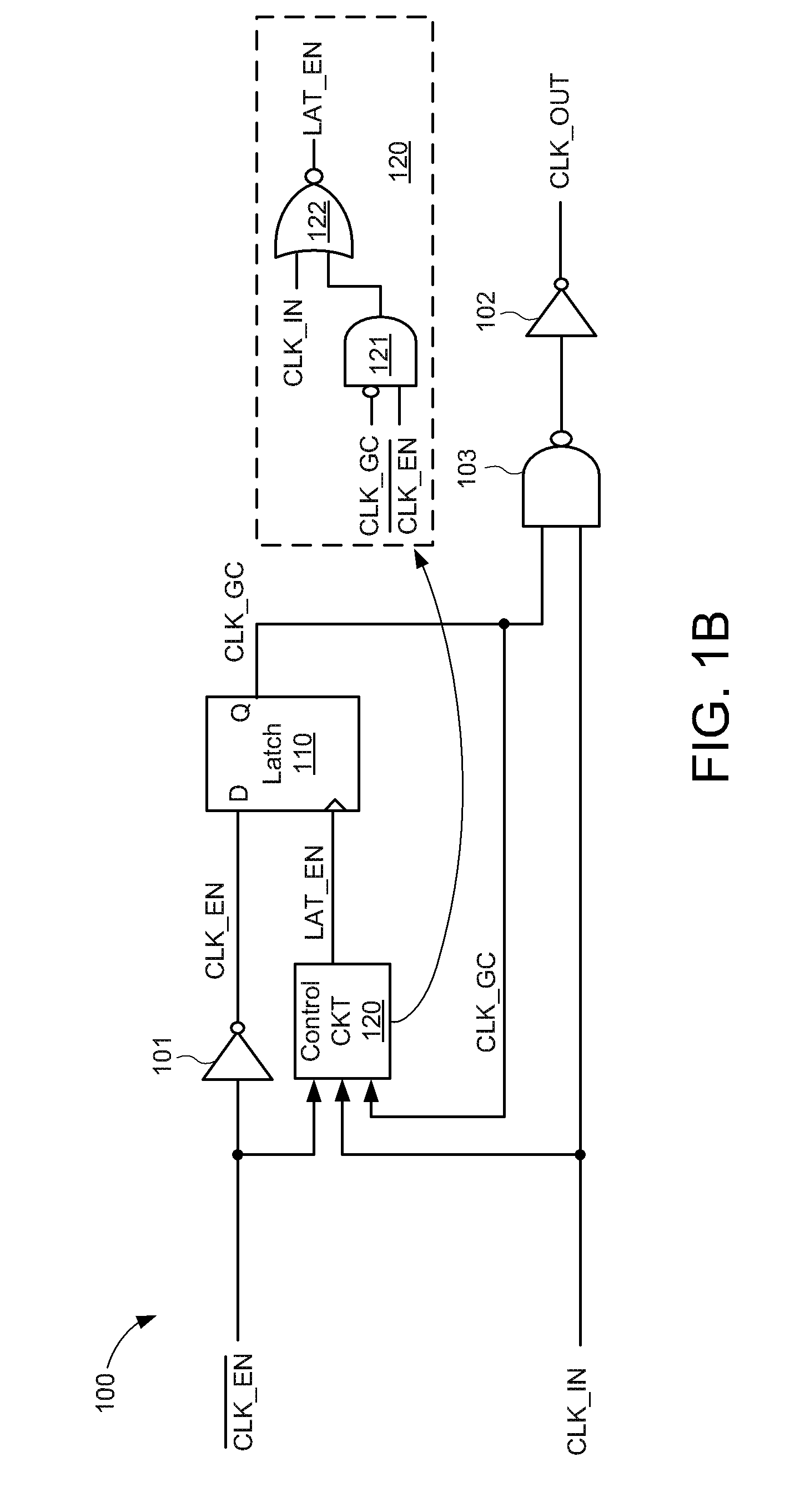
[0012]A clock-gating circuit is disclosed that may reduce unnecessary power consumption associated with clock distribution networks. For some embodiments, a partially gated clock-gating circuit is disclosed that may significantly reduce dynamic power consumption by eliminating series-connected internal logic gates that toggle between logic states in response to logic transitions of an input clock signal. More specifically, rather than controlling the operation of a clock latch's pass gate with complemented versions of the input clock signal, partially gated clock-gating circuits of the present embodiments may control the pass gate with a latch enable signal that is generated in response to the input clock signal, a latch enable signal, and a clock gating feedback signal. In this manner, undesirable toggling of nodes internal to the partially gated clock-gating circuit is avoided.

[0013]In the following description, numerous specific details are set forth such as examples of specific ...


PUM


Abstract

A clock-gating circuit is disclosed that may reduce unnecessary power consumption associated with clock distribution networks. For some embodiments, the clock-gating circuit includes a latch control circuit, a storage latch, and a logic gate. The control circuit has inputs to receive an input clock signal, a clock enable signal, and a clock gating control signal, and has an output terminal to generate a latch enable signal. The latch has a data terminal responsive to the clock enable signal, a latch enable terminal responsive to the latch enable signal, and an output to generate the clock gating control signal. The logic gate has inputs to receive the input clock signal and the clock gating control signal, and has an output terminal to generate an output clock signal. The clock-gating circuit may reduce power consumption during an enabled state by maintaining the latch enable signal at a constant logic state, thereby reducing dynamic power consumption by preventing internal logic gates from dynamically switching logic states while the input clock signal is gated.

Description

TECHNICAL FIELD[0001]The present embodiments relate generally to electronic circuits, and specifically to clock gating circuits.BACKGROUND OF RELATED ART[0002]Dynamic power consumption is an ongoing concern for integrated circuit (IC) devices, especially with the ever-increasing clock frequencies used in synchronous IC devices. Indeed, for some IC devices, more than half of the total dynamic power consumption may be attributed to clock distribution networks. One technique to reduce the dynamic power consumption of clock distribution networks is to employ clock-gating circuits (CGC) that selectively gate a number of clock signals on the IC device. More specifically, clock-gating circuits may reduce power consumption by selectively pruning an IC device's clock tree, thereby disabling portions of the clock tree so that circuit elements such as latches and / or flip-flops associated with the disabled portions do not switch between logic high and low states. Thus, preventing such latches a...

Claims


Application Information

Patent Timeline
Patent Type & Authority Applications(United States)
IPC IPC(8): H03K19/00H03K3/356
CPCH03K3/356052H03K19/0016
Inventor CAI, YANFEILI, JIDAI, QIANG
Owner QUALCOMM INC
Why Eureka
Try Eureka