Up-drawing continuous casting apparatus and up-drawing continuous casting method

Inactive Publication Date: 2015-07-23
TOYOTA JIDOSHA KK
View PDF2 Cites 0 Cited by
  • Summary
  • Abstract
  • Description
  • Claims
  • Application Information

AI Technical Summary

Benefits of technology

[0026]The first and second aspects of the present invention can provide an up-drawing continuous casting apparatus and an up-d

Problems solved by technology

However, it is difficult to form a casting in a discontinuous shape.
Further, even if the shape determining member i

Method used


Image

  • Up-drawing continuous casting apparatus and up-drawing continuous casting method
  • Up-drawing continuous casting apparatus and up-drawing continuous casting method
  • Up-drawing continuous casting apparatus and up-drawing continuous casting method

Examples


first embodiment

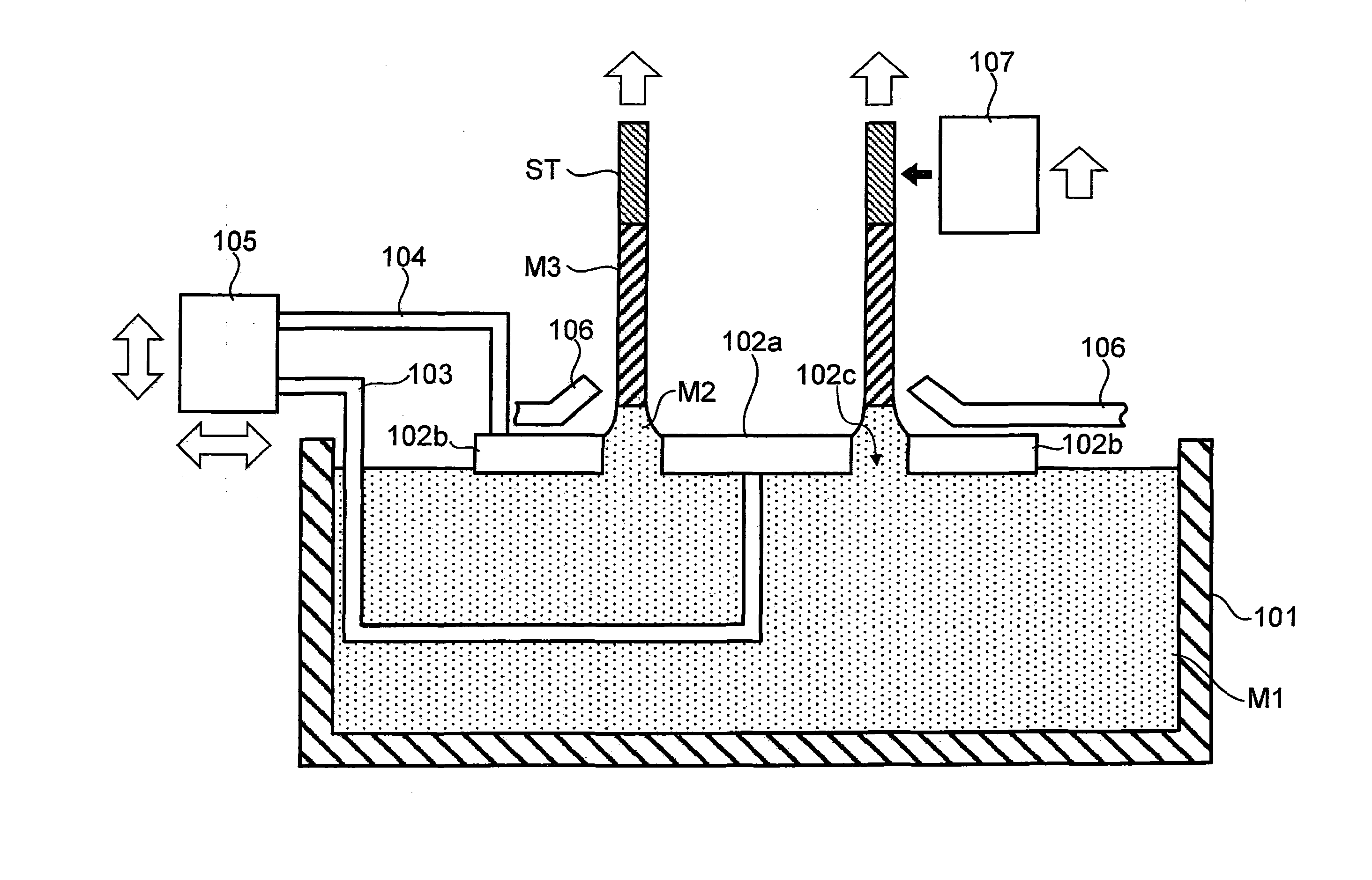
[0036]A free casting apparatus (up-drawing continuous casting apparatus) in accordance with a first embodiment will first be described with reference to FIG. 1. FIG. 1 is a cross-sectional view of the free casting apparatus in accordance with the first embodiment. As shown in FIG. 1, the free casting apparatus in accordance with the first embodiment includes a molten metal holding furnace 101, an inner shape determining member 102a, an outer shape determining member 102b, support rods 103, 104, an actuator 105, a cooling gas nozzle 106, and an impact imparting portion 107.

[0037]The molten metal holding furnace 101 houses molten metal M1 such as aluminum or its alloy and keeps the molten metal at a prescribed temperature. In an example of FIG. 1, because the molten metal holding furnace 101 is not refilled with molten metal during the casting, a surface of the molten metal M1 moves down as the casting progresses. On the other hand, the molten metal holding furnace 101 may constantly ...

second embodiment

[0057]A free casting apparatus in accordance with a second embodiment will next be described with reference to FIG. 5. FIG. 5 is a cross-sectional view of the free casting apparatus in accordance with the second embodiment. The free casting apparatus shown in FIG. 5 includes an oscillator 107a as an impact imparting portion when compared to the free casting apparatus shown in FIG. 1. Other configurations of the free casting apparatus shown in FIG. 5 are the same as the free casting apparatus shown in FIG. 1, and descriptions thereof will be omitted.

[0058]The oscillator 107a finely oscillates in a constant period, thereby imparting fine impacts to the starter ST in constant periods. Accordingly, discontinuous shapes are finely formed at constant intervals on the surface of the casting M3. In other words, fine protrusions and recesses are formed on the surface of the casting M3. This enables improvements in design and heat dissipation of the casting M3.

[0059]Further, the oscillator 10...


PUM

PropertyMeasurementUnit
Shapeaaaaaaaaaa

Abstract

An up-drawing continuous casting apparatus includes a holding furnace which holds molten metal, a guide-out member which guides the molten metal out from a surface of the molten metal held in the holding furnace, a shape determining member which is arranged to adjoin the surface of the molten metal and allows the molten metal guided out by the guide-out member to pass through the shape determining member to define a shape of a cross section of a casting, a cooling portion which cools the molten metal after the molten metal passes through the shape determining member, and an impact imparting portion which imparts an impact to the guide-out member or the casting.

Description

BACKGROUND OF THE INVENTION[0001]1. Field of the Invention[0002]The present invention relates to an up-drawing continuous casting apparatus and an up-drawing continuous casting method.[0003]2. Description of Related Art[0004]In Japanese Patent Application Publication No. 2012-61518 (JP 2012-61518 A), the inventors have been suggesting a free casting method as an epoch-making continuous casting method which requires no mold. As disclosed in JP 2012-61518 A, after a starter is immersed in a surface of molten metal, the starter is pulled up, and molten metal is then guided out following the starter via a surface film and surface tension of the molten metal. Here, the molten metal is guided out via a shape determining member arranged to adjoin the surface of molten metal and cooled, thereby enabling continuous casting for producing castings having desired cross-sectional shapes.[0005]In a conventional continuous casting method, a mold defines a cross-sectional shape and a longitudinal s...

Claims


Application Information

Patent Timeline
IPC IPC(8): B22D11/14B22D11/12B22D11/041B22D11/124
CPCB22D11/141B22D11/041B22D11/12B22D11/124B22D11/01B22D11/145
Inventor FURUKAWA, YUICHIKATO, TSUKASAMORITA, KEIICHINAKAJIMA, TETSUYAYAOKAWA, JUNIWATA, YASUSHISUGIYAMA, YOSHIO
Owner TOYOTA JIDOSHA KK
Why Eureka
Try Eureka