Porous structure provided with a pattern that is composed of conductive polymer and method of manufacturing the same

a technology of porous structure and conductive polymer, which is applied in the direction of electrolysis organic material coating, coating, therapy, etc., can solve the problems of inability to adhere to the material of the cell, the interface between the artificial device and the living organism system, and the inability of the cell to be damaged

Active Publication Date: 2013-05-23
TOHOKU UNIV
View PDF3 Cites 6 Cited by
  • Summary
  • Abstract
  • Description
  • Claims
  • Application Information

AI Technical Summary

Benefits of technology

[0032]According to a porous structure provided with a pattern that is composed of conductive polymer of the present invention, a pattern that is composed of conductive polymer can be formed on the surface of a porous body such as soft gel.
[0033]According to the method of the present invention of manufactuiring a porous structure provided with a pattern that is composed of conductive polymer, electropolymerization can be used to form a pattern that is composed of conductive polymer on the surface of a porous body such as soft gel. The electropolymerization and the dopant doping and undoping to the conductive polymer can be controlled by electricity thus achieving the formation of a flexible electrode on the surface of gel for example without requiring substrate modification or a special apparatus.

Problems solved by technology

However, an interface between the artificial device and the living organism system has various problems caused by a difference in constituting materials and a significant difference in the physical characteristic and the chemical characteristic.
For example, when a metal electrode is used to apply an electrical stimulation to cells, the cells are undesirably damaged by the toxicity of eluted metal ions or bubbles caused by electrolyzation.
If hard material such as metal or glass is used around cells involved in expansion and contraction such as muscle cells, the material not only limits the expansion and contraction but also causes a difficulty in the adhesion of the cells to the material due to expansion and contraction.
However, in the case of Nonpatent Reference 1, the gel-covered electrode, the gel, and the conductive polymer are structured in an integrated manner, thus failing to provide an elastic electrode.
All of these techniques perform patterning of conductive polymer on a rigid substrate such as glass and thus cannot be used for aqueous porous material such as gel.
Thus, in the case of an existing known technique such as a dispersion liquid coating by an inkjet printer, it is difficult to realize the pattern printing of such material.

Method used


Image

  • Porous structure provided with a pattern that is composed of conductive polymer and method of manufacturing the same
  • Porous structure provided with a pattern that is composed of conductive polymer and method of manufacturing the same
  • Porous structure provided with a pattern that is composed of conductive polymer and method of manufacturing the same

Examples


first embodiment

[0076]The following section will describe, as the first embodiment, a porous structure provided with a pattern that is composed of conductive polymer.

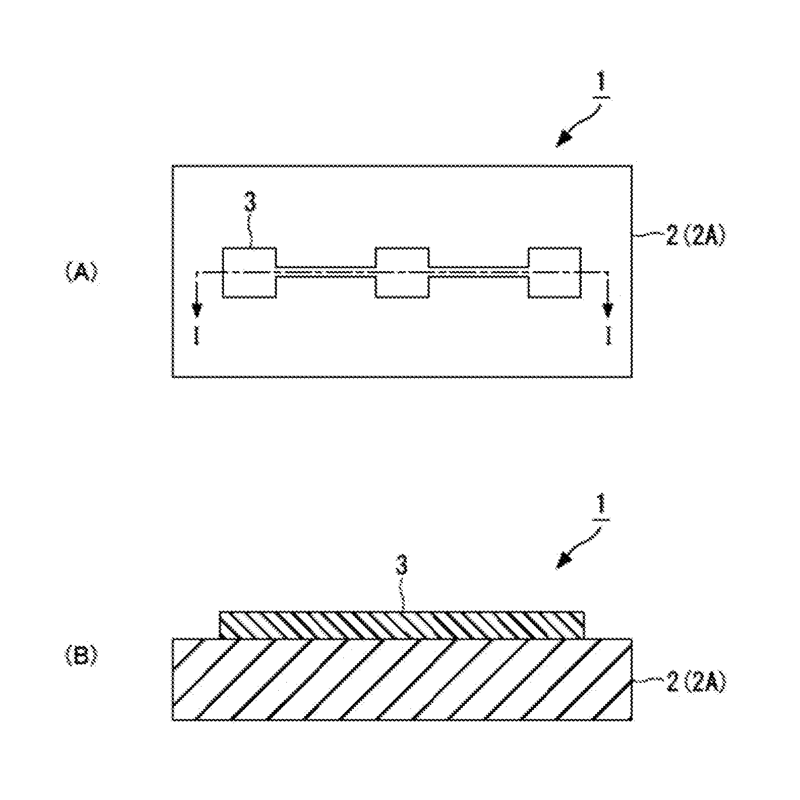
[0077]FIG. 1 illustrate the structure of a porous structure 1 including a pattern 3 that is composed of conductive polymer according to the first embodiment of the present invention wherein (A) is a top view and (B) is a cross-sectional view taken along the line I-I of (A).

[0078]As shown in FIG. 1(A), the porous structure 1 provided with the pattern 3 that is composed of conductive polymer of the present invention is comprising: a porous body 2; and the pattern 3 that is composed of conductive polymer and provided on the porous body 2. The porous body 2 is composed of porous material such as gel or hydrogel.

[0079]The gel 2A is defined as “polymer having a three-dimensional mesh structure that is insoluble in any solvent and the swelling material thereof. The mesh of the gel formed due to a change in the temperature or pH can suppress t...

second embodiment

[0090]The following section will describe the second embodiment for a method of manufacturing the porous structure 1 including the pattern 3 that is composed of conductive polymer.

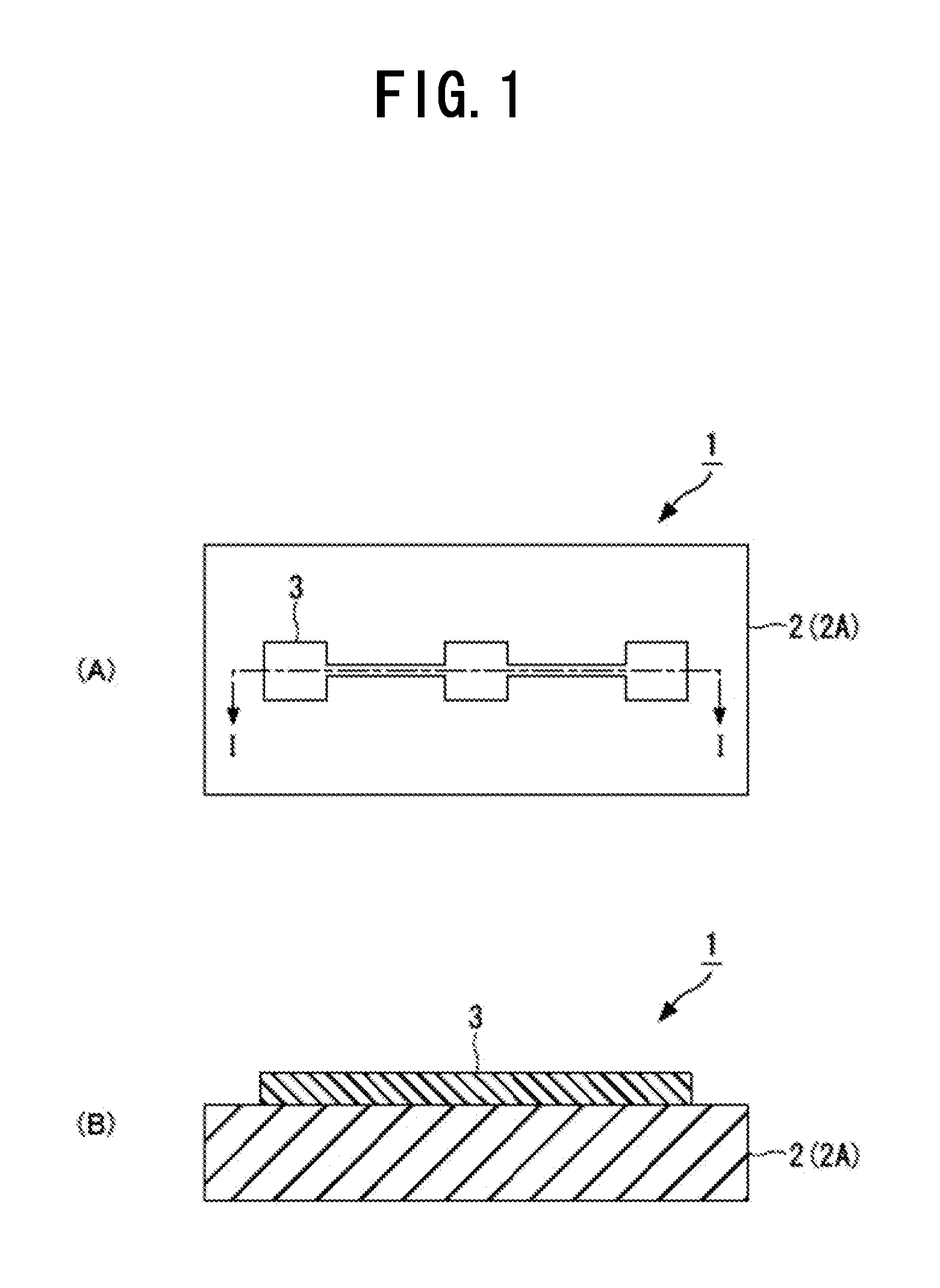
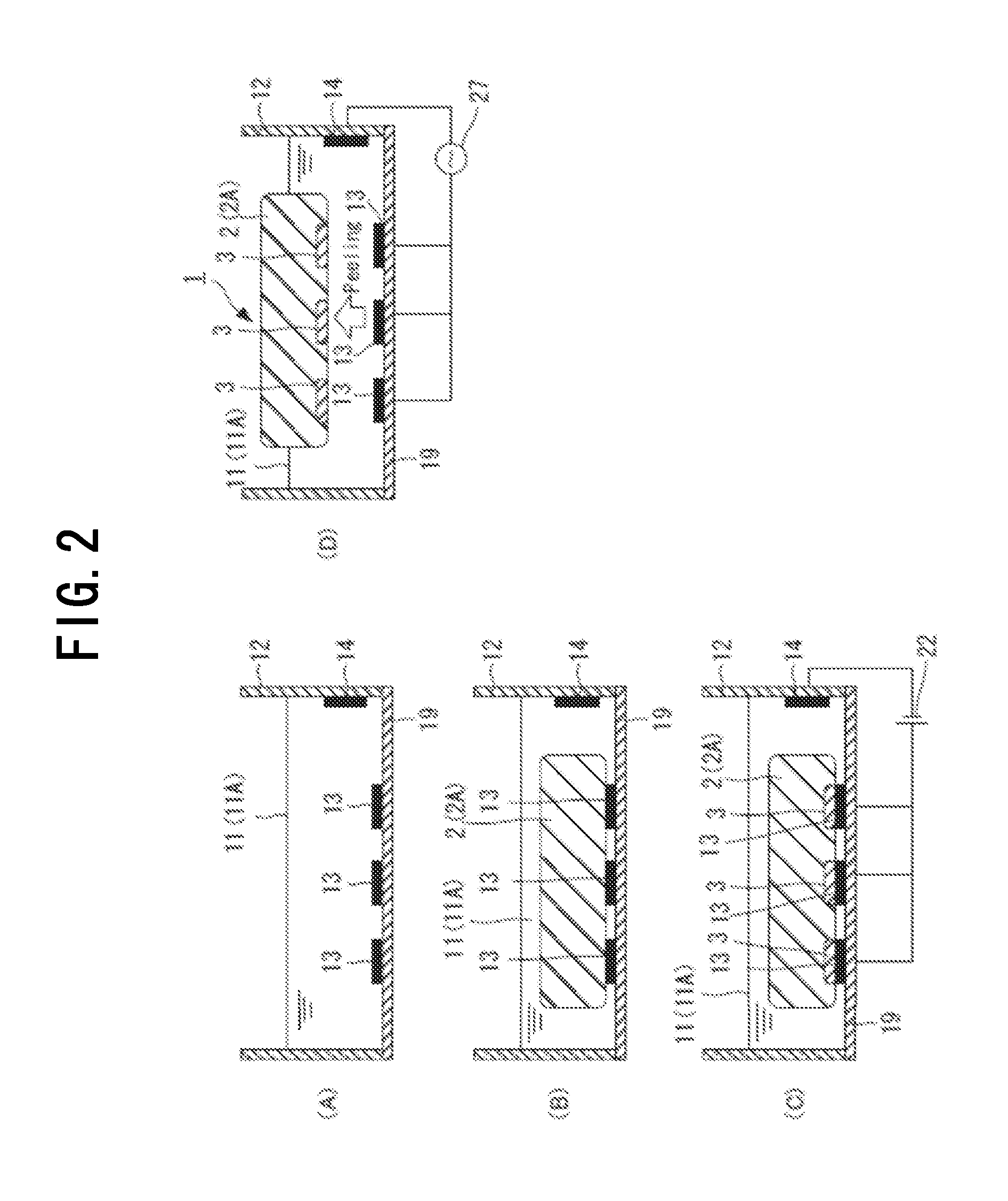
[0091]FIG. 2 is a schematic view illustrating one example of a method of manufacturing the porous structure 1 including the pattern 3 that is composed of conductive polymer in a sequential manner. FIG. 3 is a schematic view illustrating the configuration of an electropolymerization apparatus 10 used for electropolymerization. FIG. 4 is a schematic view illustrating the electrode configuration of the electropolymerization apparatus 10.

[0092]As shown in FIG. 2A, electrolyte liquid 11 including conductive polymer is placed in a container 12. The conductive polymer in the electrolyte liquid 11 may be raw material of conductive polymer. The raw material of conductive polymer may be a monomer of conductive polymer. The monomer is also called as a unit monomer and is used as a unit constituting the basic structur...

example 1

[0109]The following section will describe an Example of the present invention in more detail.

[0110]First, the following section will describe the working electrode 13, the counter electrode 14, and the reference electrode 15 used for the electropolymerization apparatus 10 as shown in FIG. 3 and FIG. 4.

(Working Electrode)

[0111]The working electrode 13 was prepared by using a slide glass as the substrate 19 to prepare, then the electrode pattern 25 composed of platinum (Pt) is fabricated on the substrate 19 by based on a series of semiconductor microfabrication techniques as shown below.

[0112]For the electrode pattern 25 as shown in FIG. 5, a mask was prepared using an emulsion mask (2 inches, made by KONICA MINOLTA) and a laser drawing apparatus (made by Heiderberg Instruments). The electrode pattern 25 was prepared using drawing preparation software (AutoCAD2009 made by Autodesk) and was used as data for the laser drawing apparatus.

[0113]The substrate 19 was coted with a positive ph...


PUM

PropertyMeasurementUnit
conductivityaaaaaaaaaa
widthaaaaaaaaaa
water content percentageaaaaaaaaaa

Abstract

A porous structure (1) provided with a pattern that is composed of a conductive polymer, which comprises a porous body (2) and a pattern (3) that is composed of a conductive polymer and arranged on the porous body (2). The porous body (2) is preferably a gel, and a dopant may be added to the pattern (3) that is composed of a conductive polymer. If an agarose gel is used as the gel (2) and a PEDOT electrode (3A) is used as the pattern (3) that is composed of a conductive polymer in the porous structure (1) which is provided with the pattern (3) that is composed of a conductive polymer, the porous structure (1) can be used as an electrode for cell stimulation. The porous structure (1) provided with the pattern (3) that is composed of a conductive polymer can be produced by an electropolymerization method.

Description

TECHNICAL FIELD[0001]The present invention relates to a porous structure provided with a pattern that is composed of conductive polymer and a method for producing the same. In particular, the present invention relates to a porous structure in which an electrode for example is formed as a pattern that is composed of conductive polymer on a porous body and a method of manufactuiring the same.BACKGROUND ART[0002]In recent years, researches have been actively performed on a device for directly controlling a living organism system such as an implanted medical apparatus or a nerve stimulation electrode. However, an interface between the artificial device and the living organism system has various problems caused by a difference in constituting materials and a significant difference in the physical characteristic and the chemical characteristic. For example, when a metal electrode is used to apply an electrical stimulation to cells, the cells are undesirably damaged by the toxicity of elut...

Claims


Application Information

Patent Timeline
Patent Type & Authority Applications(United States)
IPC IPC(8): C25D9/02H05K1/03
CPCA61N1/0496H05K1/03C25D9/02C09D5/4407H05K1/0353H05K1/0313C09D5/4476
Inventor NISHIZAWA, MATSUHIKOSEKINE, SOICHIROIDO, YUICHIRO
Owner TOHOKU UNIV
Why Eureka
Try Eureka