Wheel Loader and Wheel Loader Engine Control Method

a technology for engine control and wheel loaders, which is applied in the direction of electric control, machines/engines, instruments, etc., can solve the problems of large power consumption of large-sized wheel loaders intended to be used, limited fuel-saving performance improvement,

Active Publication Date: 2015-07-23
KOMATSU LTD
View PDF3 Cites 11 Cited by
  • Summary
  • Abstract
  • Description
  • Claims
  • Application Information

AI Technical Summary

Problems solved by technology

Therefore, improvement in the fuel-saving performance is limited.
In particular, a large-sized wheel loader intended to be used in mines and the like requires a large power not only during an excavation operation but also during a loading operation where the wheel loader approaches

Method used


Image

  • Wheel Loader and Wheel Loader Engine Control Method
  • Wheel Loader and Wheel Loader Engine Control Method
  • Wheel Loader and Wheel Loader Engine Control Method

Examples


Embodiment Construction

)

[0033]Exemplary embodiment(s) of the invention will be described below with reference to the attached drawings.

[0034]Overall Arrangement

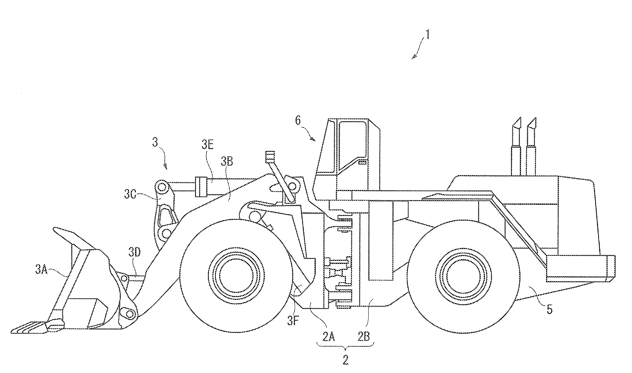
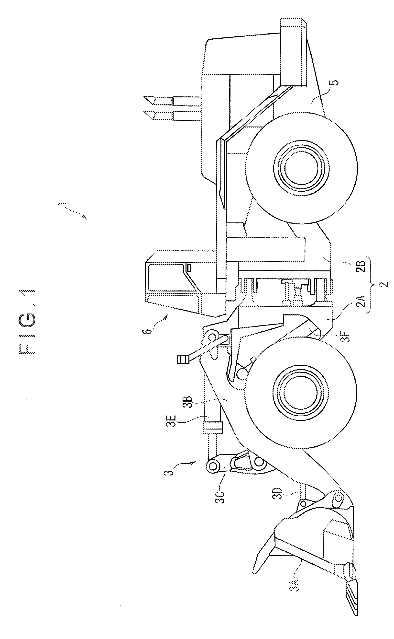
[0035]FIG. 1 is a side view of a wheel loader 1 according to a first exemplary embodiment of the invention. The wheel loader 1 is a large-sized wheel loader 1 intended to be used in mines and the like.

[0036]The wheel loader 1 includes a vehicle body 2 including a front vehicle body 2A and a rear vehicle body 2B. The front vehicle body 2A has a front side (the left side in FIG. 1) provided with hydraulic working equipment 3 including an excavating / loading bucket 3A, a boom 3B, a bell crank 3C, a connecting link 3D, a bucket cylinder 3E and a boom cylinder 3F.

[0037]The rear vehicle body 2B includes a rear vehicle body frame 5 formed from a thick metal plate or the like. The rear vehicle body frame 5 has a front side provided with a box-shaped cab 6 in which an operator is to be seated and a rear side where, for instance, an engine (not shown) and a h...


PUM


Abstract

A wheel loader includes detectors and a controller. The detectors include at least an accelerator pedal angle detector that detects an accelerator displacement. The controller includes: a state judging unit that judges from a detection result provided by the detectors whether or not the wheel loader is in an excavation operation; and a torque-curve selector. The torque-curve selector selects one excavation torque curve when the wheel loader is judged to be in the excavation operation by the state judging unit, and selects one of two or more non-excavation torque curves depending on the accelerator displacement when the wheel loader is judged not to be in the excavation operation.

Description

TECHNICAL FIELD[0001]The present invention relates to a wheel loader and an engine control method for wheel loaders.BACKGROUND ART[0002]In the latest wheel loaders, an engine torque is automatically switched to save fuel. For instance, a known method for saving fuel includes: judging whether or not a wheel loader is in an excavation operation and whether or not the wheel loader is ascending a hill; setting an engine in a high-power mode when the wheel loader is in the excavation operation or is ascending the hill; and setting the engine in a low-power mode when the wheel loader is neither in the excavation operation nor ascending the hill (see, for instance, Patent Literature 1).[0003]Another known method includes: calculating a load on a working equipment pump and / or a load on a torque converter; and variably adjusting maximum output characteristics (torque curve) of an engine so that a maximum output torque of the engine available with a current engine speed exceeds the calculated...

Claims


Application Information

Patent Timeline
IPC IPC(8): E02F9/22F02D29/02F02D41/00E02F3/28
CPCE02F9/2246E02F3/283F02D2200/10F02D41/0085F02D2700/07F02D29/02E02F9/2066F02D29/04
Inventor IMAIZUMI, MASAAKIWADA, MINORU
Owner KOMATSU LTD
Why Eureka
Try Eureka