
Heat Pump Temperature Control

a heat pump and temperature control technology, applied in heat pumps, lighting and heating apparatuses, compression machines with several condensers, etc., can solve the problems of reducing the overall efficiency associated with the operation of the underlying heat pump system, inefficient utilization, and increasing wear, so as to reduce the overshoot associated with the heat pump system and improve control and efficiency.

Active Publication Date: 2015-07-23
DCI INVESTMENTS LLC
View PDF6 Cites 9 Cited by
  • Summary
  • Abstract
  • Description
  • Claims
  • Application Information

AI Technical Summary

Benefits of technology

The present invention is a heat pump system and method of controlling it that improves efficiency and control during heating and cooling operations. The system uses a second heater to mitigate overshooting, which can happen when controlling the temperature of a fluid. The technical effect of this invention is improved performance and efficiency of heat pumps in both heating and cooling modes.

Problems solved by technology

The thermal discharge associated with such condensers is considered wasted energy in as much as the energy associated with the thermal dump is never recaptured by the system and thereby detracts from the overall efficiency associated with operation of the underlying heat pump system.
Cycling the compressor between and ON and OFF operating conditions results in inefficient utilization of the compressor and can increase wear associated with operation of the compressor which promotes premature failure of the compressor.

Method used


Image

  • Heat Pump Temperature Control
  • Heat Pump Temperature Control
  • Heat Pump Temperature Control

Examples


Embodiment Construction

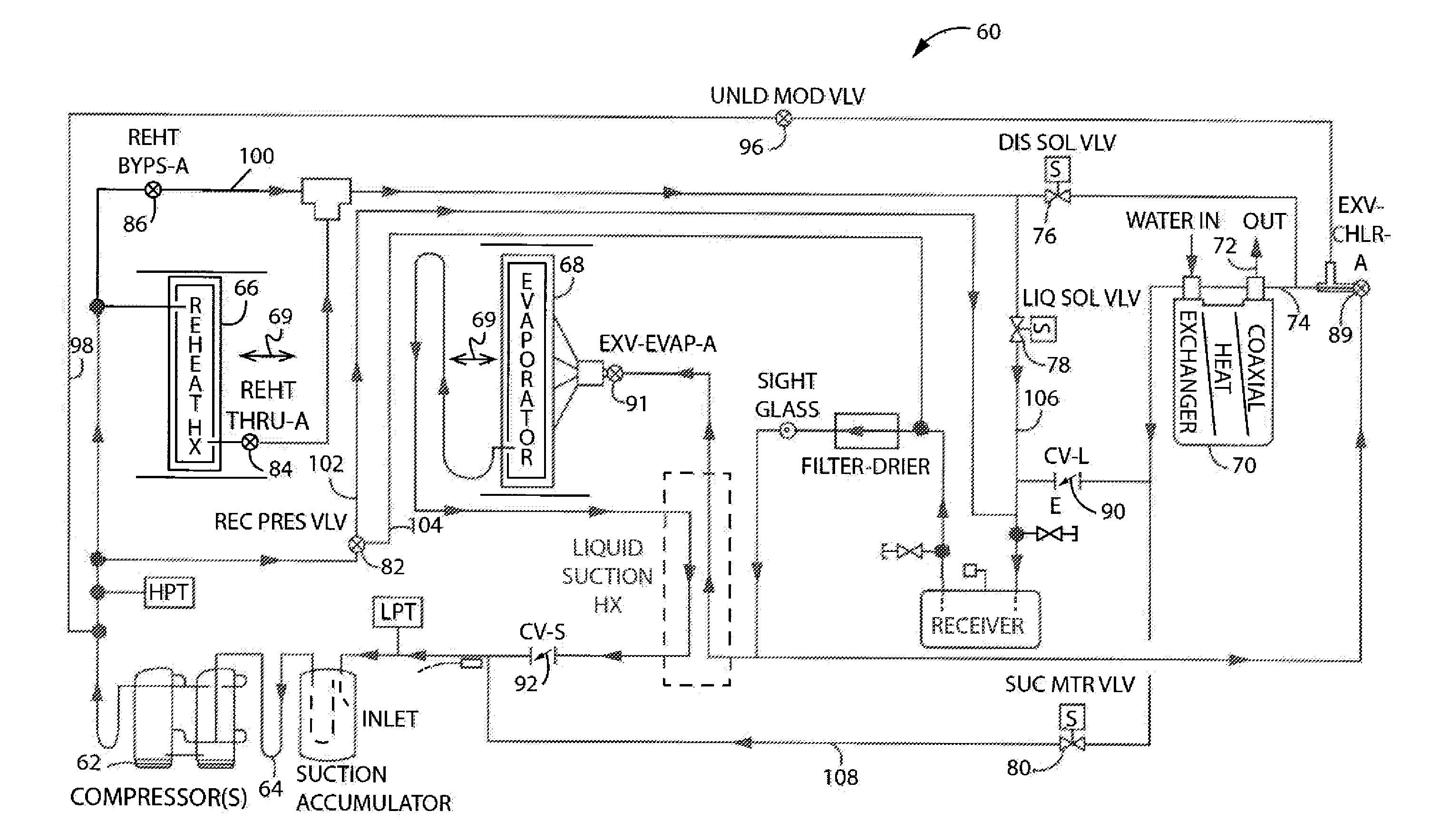
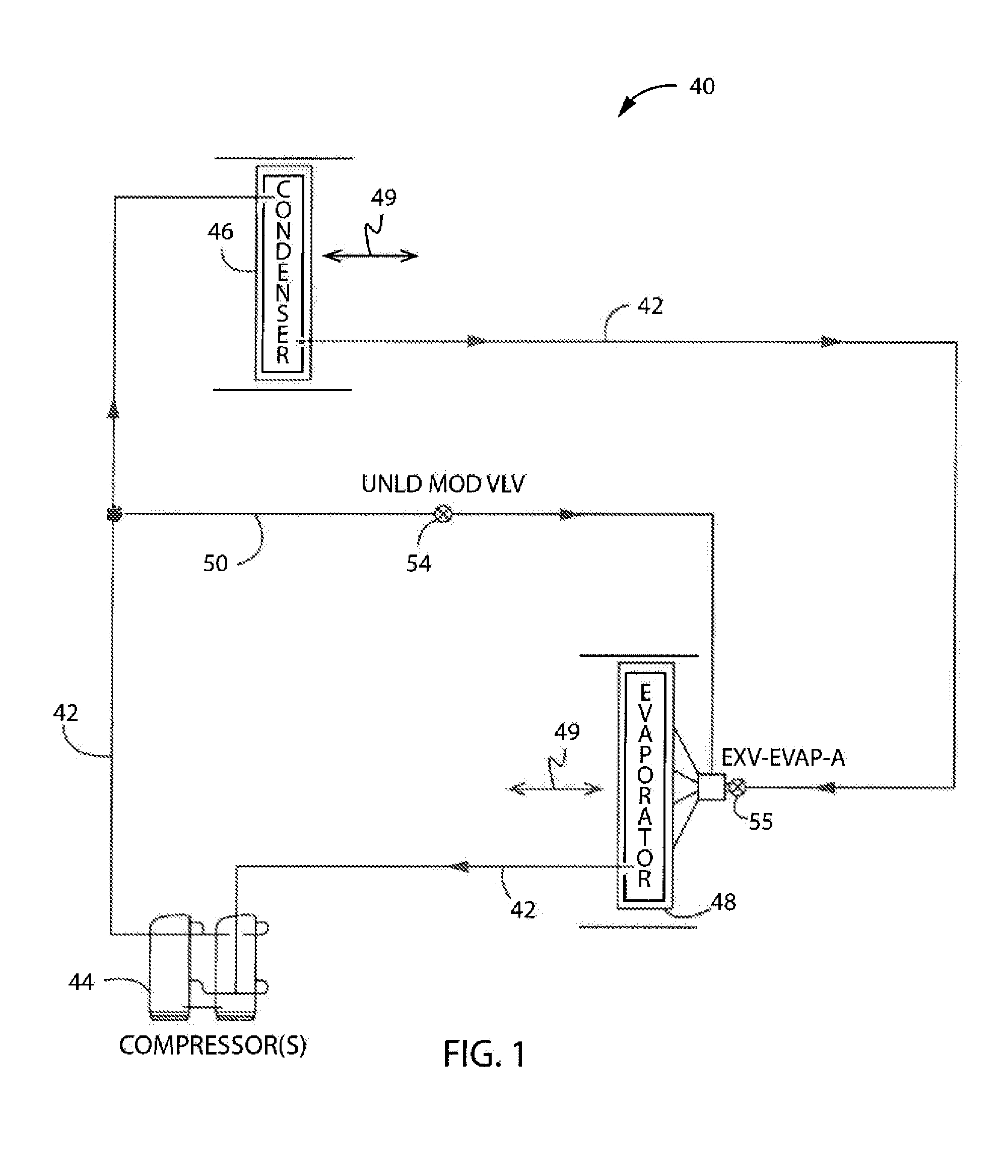
[0014]FIG. 1 shows a heat pump system 40 according to one embodiment of the present invention. System 40 includes a working fluid path or fluid path 42 associated with a compressor 44, a first heat exchanger such as a condenser 46, and the second heat exchanger such as an evaporator 48. One or both of condenser 46 and evaporator 48 can fluidly communicate with an airflow 49 associated with an environment whose temperature is intended to be manipulated. Evaporator 48 is located upstream of compressor 44 whereas condenser 46 is oriented generally downstream from compressor 44 and upstream relative to evaporator 48 with respect to the direction of the fluid flow associated with fluid path 42.

[0015]System 40 includes a bypass passage 50 that fluidly connects a portion of fluid path 42 that is downstream of compressor 44 but upstream of condenser 46 to a portion of fluid path 42 that is upstream of evaporator 48 and compressor 44. Bypass passage50 includes an unloading modulating valve a...


PUM


Abstract

A heat pump system that can be selectively utilized to discharge excessive heating and cooling capacity toward secondary devices of the system to maintain operation of the heat pump system to better manage the respective temperatures associated with the fluid flows in a manner that reduces the need for cycling the heat pump system ON and OFF to attain desired fluid output temperature manipulations.

Description

CROSS-REFERENCE TO RELATED APPLICATIONS[0001]This application claims priority to U.S. Provisional Patent Application Ser. No. 61 / 930,205 titled “HEAT PUMP TEMPERATURE CONTROL” filed on Jan. 22, 2014 and the entire contents of which is expressly incorporated herein.BACKGROUND OF THE INVENTION[0002]The present invention relates generally to heat pump systems and more particularly to a heating and cooling system constructed to generate a desired output flow temperature in a manner that maintains operation of the underlying heat pump system so as to mitigate cycling of the system between ON and OFF operating states.[0003]Many standard heat pumps utilize fixed speed compressors and multiple condensers to discharge only a required or desired amount of heat into an air flow. Using multiple condensers results in configurations wherein one or more condensers are not in the airstream associated with the fluid flow whose temperature is being manipulated such that such condensers discharge exce...

Claims


Application Information

Patent Timeline
Patent Type & Authority Applications(United States)
IPC IPC(8): F25B49/02F25B41/04F25B30/00
CPCF25B49/02F25B41/043F25B30/00F25B1/10F25B6/04F25B30/02F25B40/00F25B2339/047F25B2400/0403F25B2400/0409F25B2400/0411F25B2400/0413F25B2400/0415F25B2600/0261F25B2600/2501F25B2600/2507
Inventor BURG, CRAIG MICHAELHOGAN, JEREMYSINDELAR, HAROLD MARK
Owner DCI INVESTMENTS LLC
Learn More