
Three-dimensional-shape measurement apparatus, three-dimensional-shape measurement method, and non-transitory computer-readable storage medium

a three-dimensional shape and measurement method technology, applied in the direction of measurement devices, instruments, image analysis, etc., can solve the problems of difficult measurement so as to satisfy the condition, deterioration of measurement accuracy, and considerable limitation of the application possibilities of three-dimensional measurement apparatus, so as to achieve stable three-dimensional measurement and high accuracy

Active Publication Date: 2015-07-23
CANON KK
View PDF11 Cites 95 Cited by
  • Summary
  • Abstract
  • Description
  • Claims
  • Application Information

AI Technical Summary

Benefits of technology

The patent aims to solve the problem of accurately measuring the shape of objects that are not perfectly transparent. It provides a technique that can measure the shape of objects in a real-life environment without requiring extensive preparation. This technique allows for high-accuracy measurements of objects that are not perfectly transparent.

Problems solved by technology

In general, as for a measurement target made of a material such as a plastic or the like, the measurement accuracy deteriorates or the measurement itself becomes impossible due to a phenomenon called subsurface scattering or internal scattering.
At the time of measurement of such a target, processing of the target, for example, by applying in advance a white powder or the like to the surface of the target is required, thereby considerably limiting the application possibilities of the three-dimensional measurement apparatus.
Performing the measurement so as to satisfy the condition can be difficult.
Similarly, in the methods described in non-patent literatures 1 and 2, it is necessary to perform shooting by projecting a number of patterned light beams in order to measure the overall target object, resulting in a long measurement time.

Method used


Image

  • Three-dimensional-shape measurement apparatus, three-dimensional-shape measurement method, and non-transitory computer-readable storage medium
  • Three-dimensional-shape measurement apparatus, three-dimensional-shape measurement method, and non-transitory computer-readable storage medium
  • Three-dimensional-shape measurement apparatus, three-dimensional-shape measurement method, and non-transitory computer-readable storage medium

Examples


first embodiment

[0033]In this embodiment, a space-division pattern intended to cause hardly any encoding error is projected into a measurement space to divide the measurement space including a measurement target object into a predetermined number of regions. Then, the three-dimensional shape of the measurement target object (the three-dimensional coordinates of the surface of the measurement target object) is precisely calculated by projecting a coordinate-detection pattern unique for each divided region.

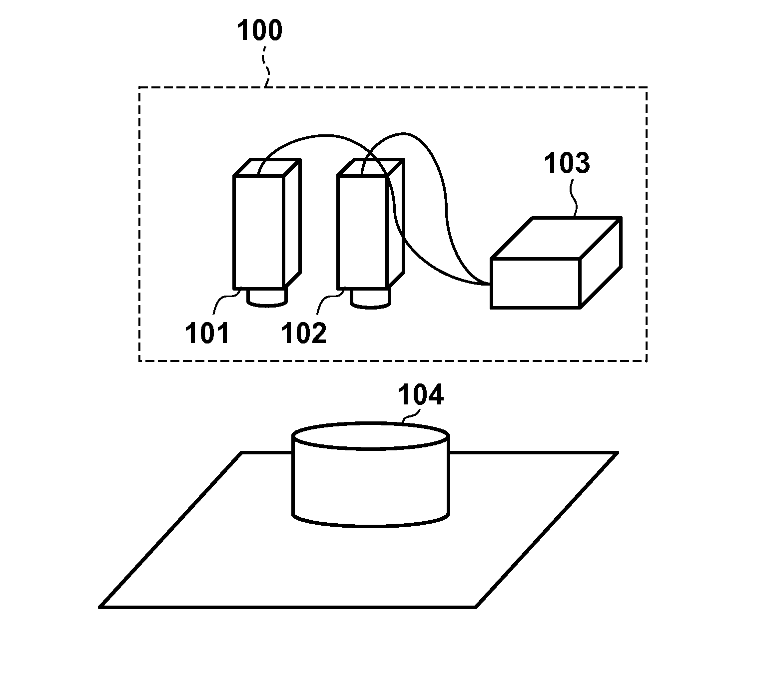
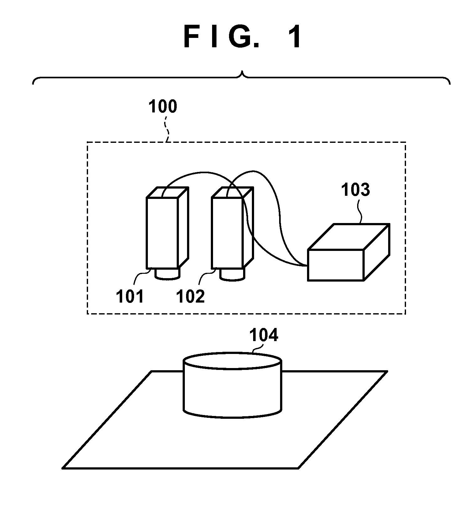
[0034]An example of the configuration of a system according to this embodiment will be described with reference to FIG. 1. A system 100 according to this embodiment includes a projection unit 101 for projecting patterned light onto a measurement target object 104, an image-capturing unit 102 for capturing an image of the measurement target object 104 onto which the patterned light has been projected, and a control apparatus 103 for performing three-dimensional-shape measurement of the measurement t...

second embodiment

[0085]In this embodiment, at the time of projecting a space-division pattern, the boundary portion between the bright and dark portions is masked so as not to project the space-division pattern. This further reduces the probability of an encoding error at the time of space-division, thereby making it possible to calculate the three-dimensional coordinates of a measurement target object surface more stably.

[0086]The difference from the first embodiment will be mainly described below, and a description of the same points as in the first embodiment will be omitted. That is, details are the same as in the first embodiment unless specifically stated otherwise.

[0087]FIGS. 8A and 8B each show an example of a mask pattern used to mask a pattern to be projected by a projection unit 101. FIG. 8A shows an example of a mask pattern used to mask a Gray code pattern. FIG. 8B shows an example of a mask pattern used to mask a shift Gray code pattern.

[0088]When the mask pattern is used to mask and p...

third embodiment

[0104]In the first embodiment, the coordinate-detection pattern formed from a plurality of line segments is used, as shown in FIG. 6. In this embodiment, as shown in FIG. 11, a coordinate-detection pattern formed from a plurality of broken lines is used. By projecting such coordinate-detection pattern onto a measurement target object 104, the influence of internal scattering occurring in the measurement target object 104 is removed, resulting in more accurate calculation of three-dimensional coordinates on the surface of the measurement target object 104.

[0105]The difference from the first embodiment will be mainly described below, and a description of the same points as in the first embodiment will be omitted. That is, details are the same as in the first embodiment unless specifically stated otherwise.

[0106]In this embodiment, a projection pattern generation unit 202 supplies, to a projection unit 101, the coordinate-detection pattern formed from the plurality of broken lines show...


PUM


Abstract

A first image of a space onto which a first light pattern formed from bright and dark portions and a coordinate-detection pattern projected onto each region of the space divided by the first pattern have been projected is acquired. A second image is acquired of the space onto which a second light pattern having a boundary position between bright and dark portions that is different from that of the first pattern, and a coordinate-detection pattern projected onto each region of the space divided by the second pattern have been projected. One of the first image and the second image is selected to perform three-dimensional shape measurement of an object included in the space based on the selection image.

Description

BACKGROUND OF THE INVENTION[0001]1. Field of the Invention[0002]The present invention generally relates to a three-dimensional-shape measurement apparatus, a three-dimensional-shape measurement method, and a non-transitory computer-readable storage medium, particular to a technique for measuring the three-dimensional shape of a measurement target object.[0003]2. Description of the Related Art[0004]There is widely known a three-dimensional measurement apparatus that obtains three-dimensional coordinates by the triangulation principle based on a position where an image capturing unit observes reflection light when a projection unit such as a projector projects a striped pattern typified by a space encoding method or the like onto a measurement target. With such an apparatus, the measurement accuracy of three-dimensional coordinates largely depends on the material of a measurement target.[0005]In general, as for a measurement target made of a material such as a plastic or the like, the...

Claims


Application Information

Patent Timeline
Patent Type & Authority Applications(United States)
IPC IPC(8): G01B11/25
CPCG01B11/25G01B11/2513G06T7/50G01B11/2531G01B11/2536G01B11/254G06T3/00G06T7/00G06T7/60
Inventor KOBAYASHI, TOSHIHIROHIGO, TOMOAKIYAMASAKI, MASAYOSHI
Owner CANON KK
Features
  • Generate Ideas
  • Intellectual Property
  • Life Sciences
  • Materials
  • Tech Scout
  • Unparalleled Data Quality
  • Higher Quality Content
  • 60% Fewer Hallucinations
Learn More