
Low Pressure Pilot Operated Relief Valve

a pilot-operated, relief valve technology, applied in the direction of valve housing, valve operating means/releasing devices, functional valve types, etc., can solve the problems of inferior flow rate efficiency of valves, inability to provide means for controlling the expansion of traversing fluid, etc., to achieve the effect of increasing the efficiency of fluid flow

Active Publication Date: 2015-07-23
EMERSON VULCAN HLDG LLC
View PDF5 Cites 10 Cited by
  • Summary
  • Abstract
  • Description
  • Claims
  • Application Information

AI Technical Summary

Benefits of technology

The patent is for a new type of valve that improves the flow of fluid through it. It also helps manage the energy of the fluid so it can flow in a controlled direction. This design can be used in any system that needs to control fluid flow direction.

Problems solved by technology

Additionally, such designs typically do not provide means for controlling the expansion of the traversing fluid, and commonly rely solely on a cylindrical curtain area to allow the traversing fluid to pass into the valve body.
Such valves deliver inferior flow rate efficiency through the valve body and, therefore, it would be desirable to have a valve body that provides a means to control the expansion of the traversing fluid through the valve body.

Method used


Image

  • Low Pressure Pilot Operated Relief Valve
  • Low Pressure Pilot Operated Relief Valve
  • Low Pressure Pilot Operated Relief Valve

Examples


Embodiment Construction

[0015]Before any embodiments of the invention are explained in detail, it is to be understood that the invention is not limited in its application to the details of construction and the arrangement of components set forth in the following description or illustrated in the following drawings. The invention is capable of other embodiments and of being practiced or of being carried out in various ways. Also, it is to be understood that the phraseology and terminology used herein is for the purpose of description and should not be regarded as limiting. The use of “including,”“comprising,” or “having” and variations thereof herein is meant to encompass the items listed thereafter and equivalents thereof as well as additional items. Unless specified or limited otherwise, the terms “mounted,”“connected,”“supported,” and “coupled” and variations thereof are used broadly and encompass both direct and indirect mountings, connections, supports, and couplings. Further, “connected” and “coupled”...


PUM


Abstract

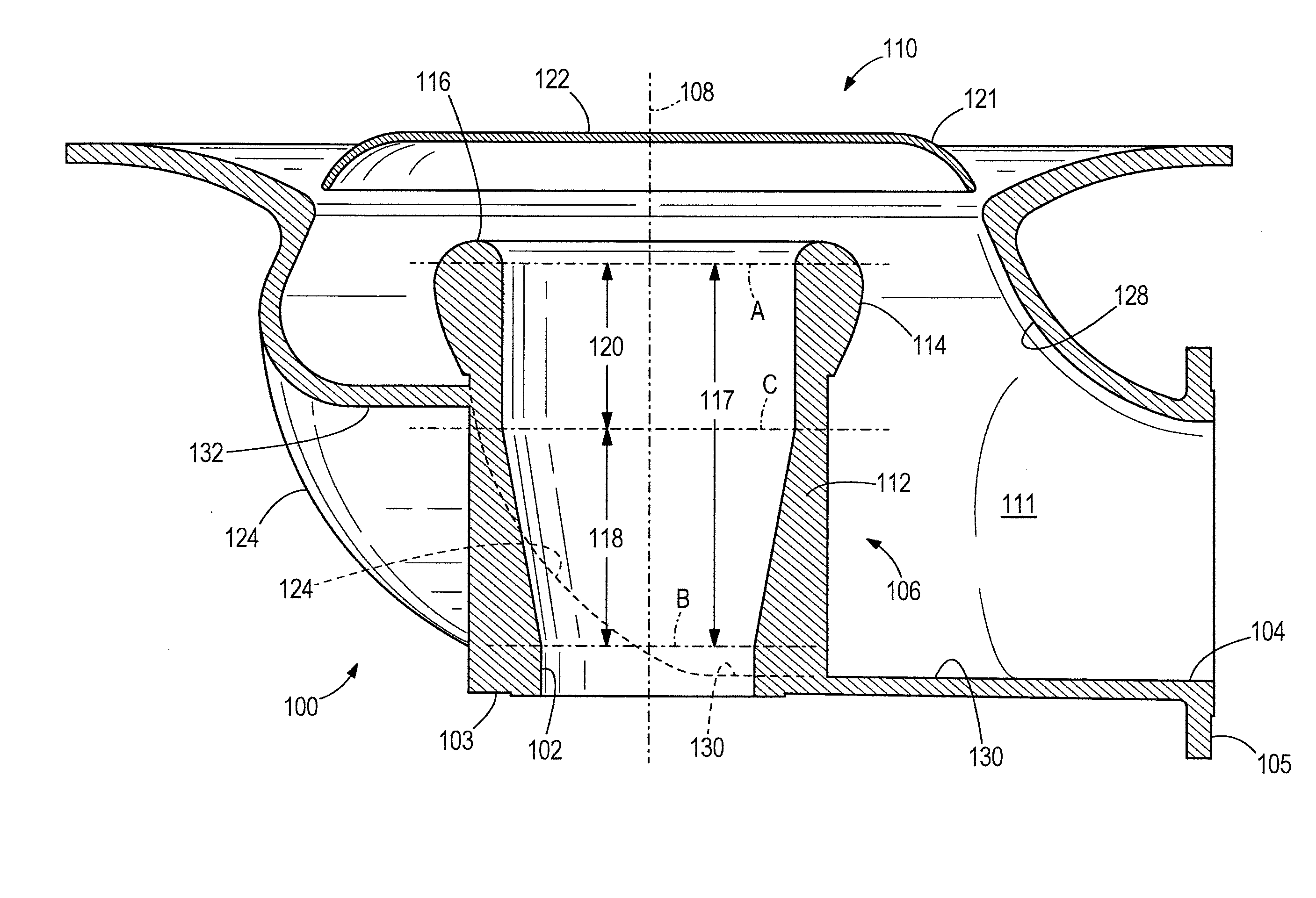
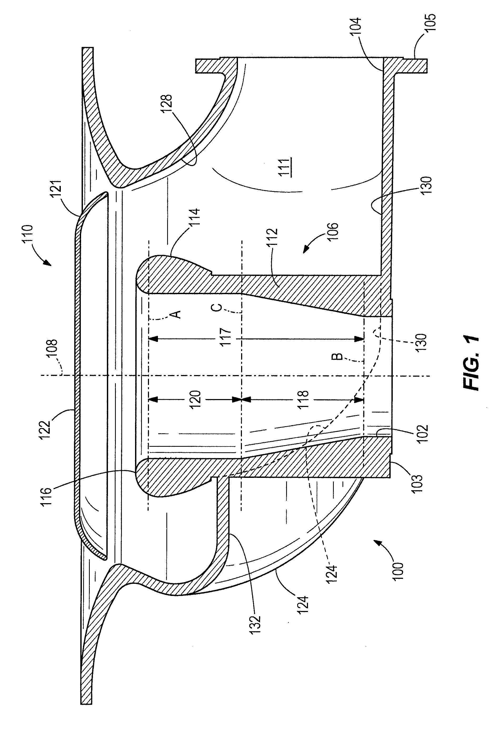
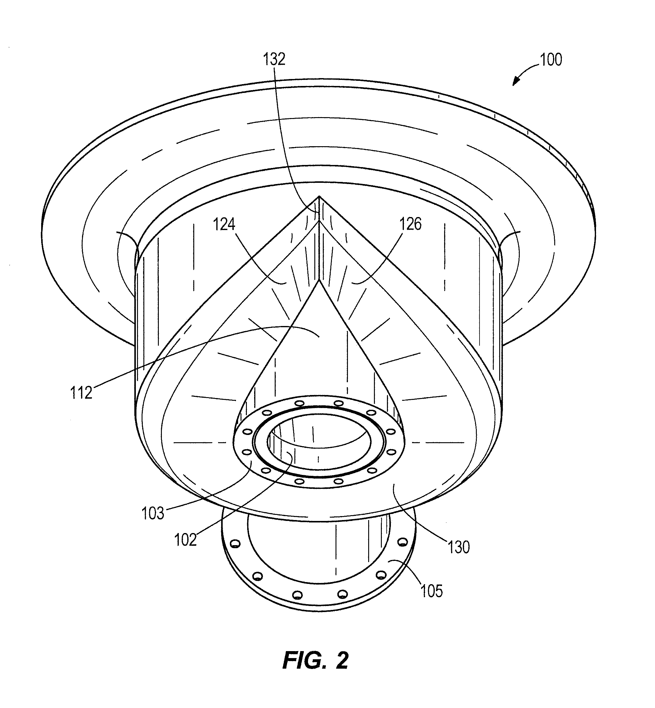
Embodiments of the invention provide a relief valve body arranged for connecting to a pressure vessel. The relief valve body includes an inlet configured to connect to a pressure vessel and an integrated nozzle downstream from the inlet and extending along an axis. The integrated nozzle includes a nozzle exterior surface, a nozzle bulb, and a valve seat and defines a nozzle expansion region. The relief valve body further includes a redirecting pallet, a valve interior surface having at least one ramped portion downstream from the integrated nozzle and redirecting pallet, and an outlet downstream from the at least one ramped portion.

Description

RELATED APPLICATION[0001]This application claims the benefit of U.S. Provisional Application No. 61 / 928,850 filed on Jan. 17, 2014, the entire disclosure of which is hereby incorporated herein by reference.BACKGROUND[0002]The present disclosure relates generally to relief valves for pressure vessels and, in particular, to pilot operated relief valves.[0003]Current manufacturers commonly employ valve body designs intended to direct a fluid flow at a right angle with respect to an inlet without consideration to an expansion of the traversing fluid. Additionally, such designs typically do not provide means for controlling the expansion of the traversing fluid, and commonly rely solely on a cylindrical curtain area to allow the traversing fluid to pass into the valve body. Such valves deliver inferior flow rate efficiency through the valve body and, therefore, it would be desirable to have a valve body that provides a means to control the expansion of the traversing fluid through the va...

Claims


Application Information

Patent Timeline
IPC IPC(8): G05D16/16
CPCG05D16/16F16K31/1266F16K1/06F16K27/0236Y10T137/7764F16K17/02F16K27/02
Inventor MCNEELY, MICHAELMARCELLUS, MICHAELSIMPSON, STEPHEN
Owner EMERSON VULCAN HLDG LLC
Learn More