Method of beamforming and 3D antenna array

a technology of communication nodes and antenna arrays, applied in the field of beamforming of communication nodes and 3d antenna arrays, can solve the problems of large overhead and high complexity of these processes, and achieve the effects of reducing control and computation complexity, feedback overhead, and extending communication coverag

Inactive Publication Date: 2015-07-23
ELECTRONICS & TELECOMM RES INST
View PDF9 Cites 11 Cited by
  • Summary
  • Abstract
  • Description
  • Claims
  • Application Information

AI Technical Summary

Benefits of technology

[0010]The present invention has been made in an effort to provide a method of beamforming and a 3D antenna array having advantages of extending communication coverage and reducing control and computation complexity and feedback overhead.

Problems solved by technology

Overhead and complexity for these processes are large and high.

Method used


Image

  • Method of beamforming and 3D antenna array
  • Method of beamforming and 3D antenna array
  • Method of beamforming and 3D antenna array

Examples


Embodiment Construction

[0036]In the following detailed description, only certain exemplary embodiments of the present invention have been shown and described, simply by way of illustration. As those skilled in the art would realize, the described embodiments may be modified in various different ways, all without departing from the spirit or scope of the present invention. Accordingly, the drawings and description are to be regarded as illustrative in nature and not restrictive. Like reference numerals designate like elements throughout the specification.

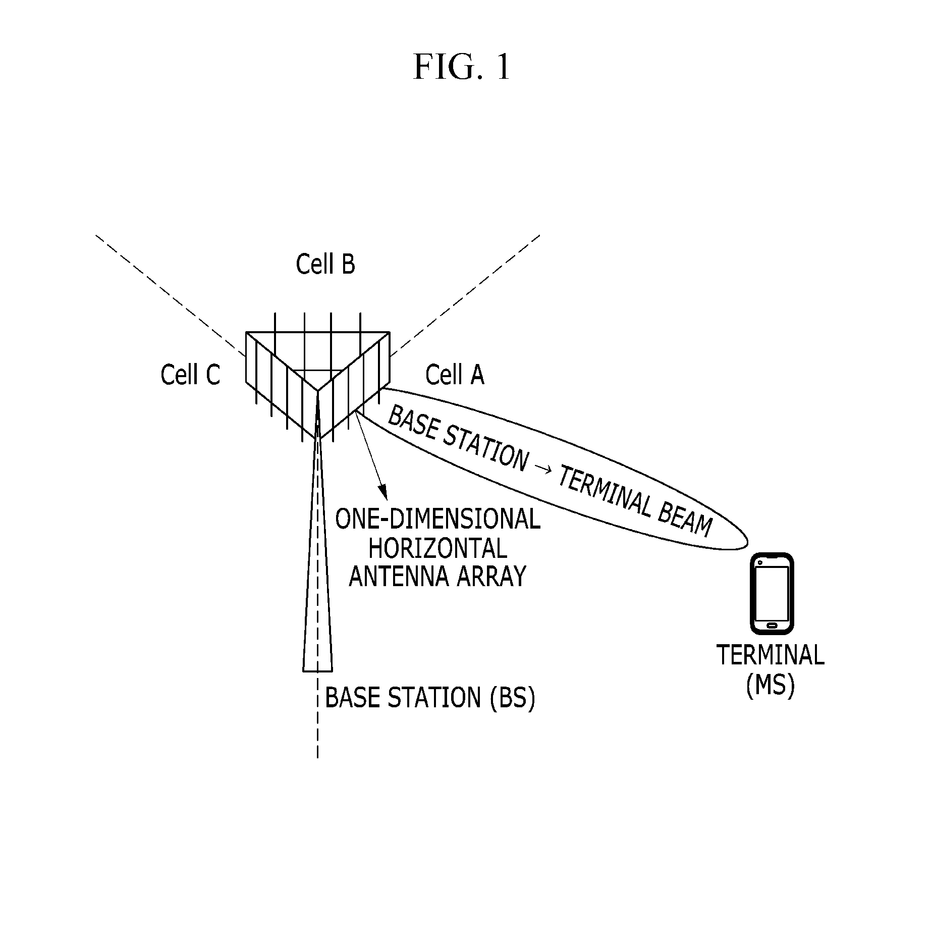
[0037]Throughout the specification, a terminal may refer to a mobile terminal (MT), a mobile station (MS), a subscriber station (SS), a portable subscriber station (PSS), an access terminal (AT), user equipment (UE), and the like, and may also include all or a part of the functions of the MT, MS, SS, PSS, AT, UE, and the like.

[0038]Further, a base station (BS) may refer to a node B (NodeB), an evolved node B (eNodeB), an access point (AP), a radio access s...


PUM


Abstract

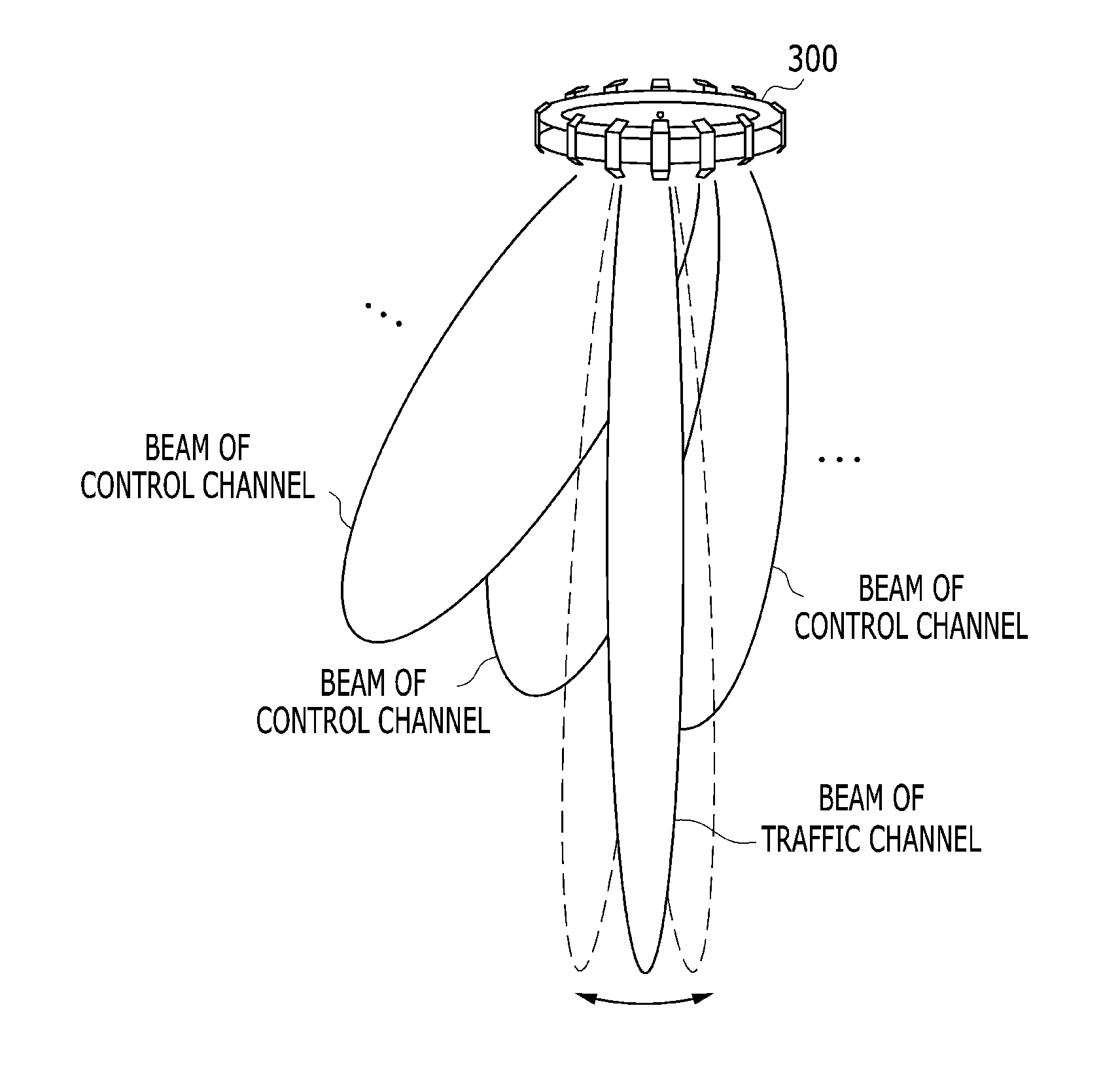
Disclosed herein are a method of beamforming and a 3D antenna array. The method includes: transmitting a first control channel; receiving first feedback information on a first antenna set and a first precoding scheme of a plurality of antenna sets included in the 3D antenna array, which are determined based on the first control channel, from a first communication node different from the communication node; and beamforming a traffic channel to be transmitted to the first communication node using the first antenna set and the first precoding scheme.

Description

CROSS-REFERENCE TO RELATED APPLICATION[0001]This application claims priority to and the benefit of Korean Patent Application No. 10-2014-0006881 filed in the Korean Intellectual Property Office on Jan. 20, 2014, the entire contents of which are incorporated herein by reference.BACKGROUND OF THE INVENTION[0002](a) Field of the Invention[0003]The present invention relates to a method of beamforming of a communication node and a 3D antenna array included in a communication node which performs wireless communication.[0004](b) Description of the Related Art[0005]To improve a data rate and quality of a communication link in a mobile communication network and a wireless local area network, a closed-loop spatial multiplexing (CL-SM) scheme or a closed-loop beamforming (CL-BF) scheme using multiple input multiple output (MIMO) antennas and channel state feedback information on those antennas, has been applied. The CL-SM is a scheme of transmitting multiple data streams in parallel using the ...

Claims


Application Information

Patent Timeline
Patent Type & Authority Applications(United States)
IPC IPC(8): H04W16/28H04B7/04
CPCH04W16/28H04W74/002H04B7/0456H04B7/0417H04B7/0413H04B7/0617H04B7/0619H04B7/0634
Inventor LIM, KWANG JAELEE, ANSEOKSHIN, WOORAM
Owner ELECTRONICS & TELECOMM RES INST
Why Eureka
Try Eureka