
Four-beam vortex field conformal reflector antenna based on metasurface

A metasurface and vortex field technology, applied to antennas, devices that enable antennas to work in different bands at the same time, electrical components, etc., can solve the problem of small radiation coverage of vortex electromagnetic waves, and achieve the effect of widening the communication coverage

Active Publication Date: 2020-10-09
XIDIAN UNIV
View PDF9 Cites 0 Cited by
  • Summary
  • Abstract
  • Description
  • Claims
  • Application Information

AI Technical Summary

Problems solved by technology

[0008] The purpose of the present invention is to overcome the deficiencies in the above-mentioned prior art, and propose a four-beam vortex field conformal reflector antenna based on metasurfaces, which is used to solve the problems in the prior art due to the small number of vortex electromagnetic waves generated. Small technical issues with radiation coverage

Method used


Image

  • Four-beam vortex field conformal reflector antenna based on metasurface
  • Four-beam vortex field conformal reflector antenna based on metasurface
  • Four-beam vortex field conformal reflector antenna based on metasurface

Examples


Embodiment 1

[0032] Embodiment 1 of the present invention will be further described below in conjunction with the drawings and specific embodiments.

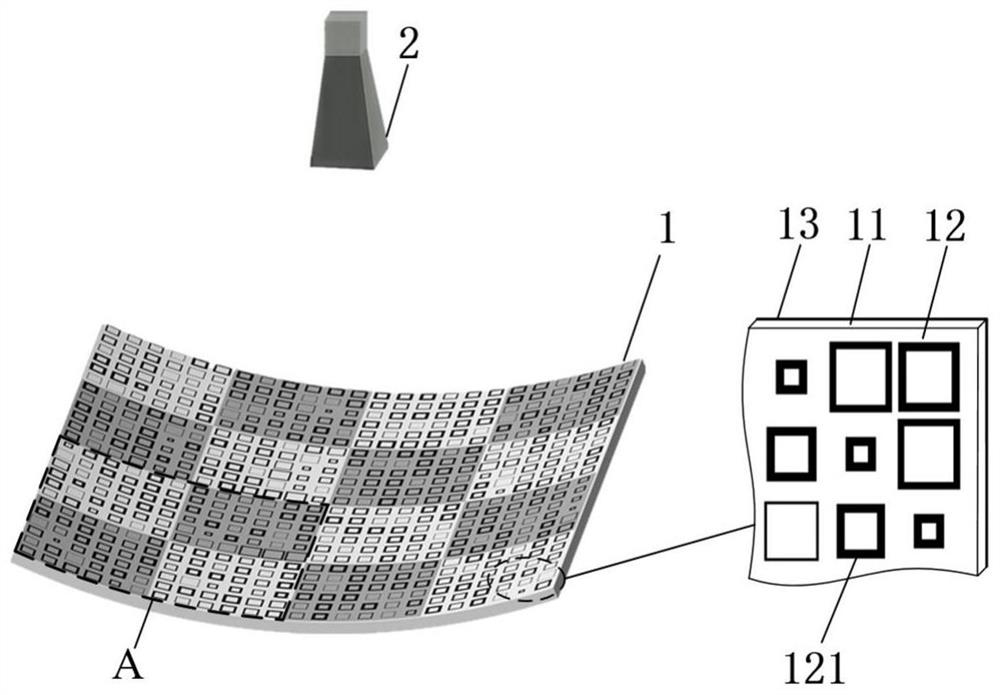
[0033] refer to figure 1 , Embodiment 1 of the present invention includes a reflector 1 and a feed source 2;

[0034] The reflector 1 adopts a metasurface structure, including a dielectric substrate 11 in the shape of a parabolic cylinder, and adopts a dielectric material with a thickness of 0.5mm, a relative permittivity of 4.4, and a relative magnetic permeability of 1, and its normal direction points to A metal ring array 12 is printed on one side of the aperture surface, and a metal base plate 13 is printed on the other side; the metal ring array 12 is composed of a plurality of metal ring microstructures 121 uniformly and periodically arranged in different sizes, wherein the metal ring The array 12 is divided into a plurality of regions, and each region is composed of 2×2 subregions, such as figure 1 Among them, A represents a region,...

Embodiment 2

[0050] The present invention will be further described below in conjunction with the accompanying drawings and specific embodiments.

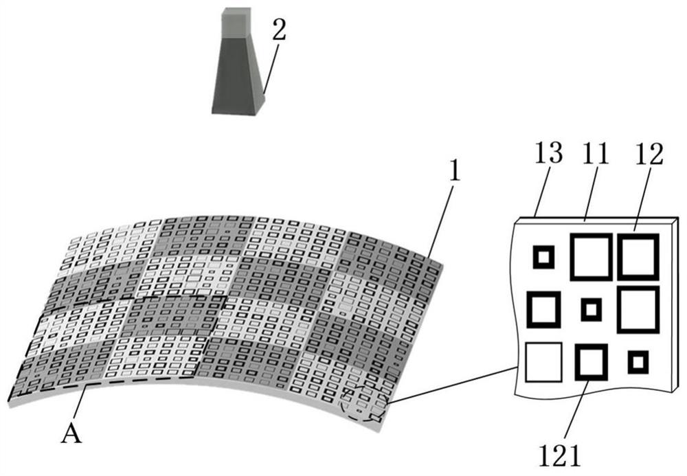
[0051] refer to figure 2 , the present invention includes a reflector 1 and a feed source 2;

[0052] The reflector 1 adopts a metasurface structure, including a dielectric substrate 11 in the shape of a parabolic cylinder, and adopts a dielectric material with a thickness of 0.5mm, a relative permittivity of 4.4, and a relative magnetic permeability of 1, and its normal direction deviates from A metal ring array 12 is printed on one side of the aperture surface, and a metal base plate 13 is printed on the other side; the metal ring array 12 is composed of a plurality of metal ring microstructures 121 uniformly and periodically arranged in different sizes, wherein the metal ring The array 12 is divided into a plurality of areas, each area is composed of 2×2 sub-areas, figure 2 Among them, A represents a region, and the structure of the meta...


PUM


Abstract

The invention provides a metasurface-based four-beam eddy field conformal reflector antenna, so as to solve the problem of a small radiation coverage of a conformal eddy field antenna in the prior art. The metasurface-based four-beam eddy field conformal reflector antenna comprises a mirror and a feed source, wherein the mirror adopts a parabolic cylindrical metasurface structure and comprises a parabolic cylindrical dielectric substrate, one side, pointing to an aperture surface or deviating from the aperture surface, of a normal positive direction is printed with a metal ring array, the other side is printed with a metal backplane, the metal ring array is divided to i*i areas, each area is formed by 2*2 subareas, each subarea comprises j*j uniformly-distributed metal ring microstructures, and the initial phase difference between phase compensation values of metal ring microstructures in two subareas on a main diagonal and metal ring microstructures in two subareas on a slave diagonalin each area is 180 DEG. Eddy beams can be generated in four directions, the radiation coverage is increased, and conformal loading on a non-planar carrier is realized.

Description

technical field [0001] The invention belongs to the technical field of antennas, and relates to a four-beam vortex field conformal reflector antenna, which can be used in the communication field where the antenna is required to be loaded on a conformal carrier. [0002] technical background [0003] Due to the good orthogonality between different modes of vortex electromagnetic waves, a large number of channels with the same frequency can be formed, which greatly improves the communication capacity. [0004] The existing technologies for generating vortex electromagnetic beams mainly include array antennas, lens antennas, and reflector antennas. The generation of vortex beams by array antennas requires complex phase shifting and feeding networks. Not only must the phase relationship between element antennas be considered, but also To consider the mutual coupling between element antennas, the technical solution is very complicated, which is not conducive to practical applicati...

Claims


Application Information

Patent Timeline
Patent Type & Authority Patents(China)
IPC IPC(8): H01Q19/13H01Q5/55
CPCH01Q5/55H01Q19/13
Inventor 杨锐高鸣高东兴顾宸光
Owner XIDIAN UNIV
Learn More