
Wireless communication apparatus and method for controlling wireless communication apparatus

Inactive Publication Date: 2015-07-23
PANASONIC INTELLECTUAL PROPERTY MANAGEMENT CO LTD
View PDF2 Cites 0 Cited by
  • Summary
  • Abstract
  • Description
  • Claims
  • Application Information

AI Technical Summary

Benefits of technology

The present invention aims to simplify the circuit configuration, lower electricity consumption, and prevent device configuration from increasing while performing wireless communication to control multiple household electrical appliances. It ensures stable communication under a multipath environment.

Problems solved by technology

In the case of a wireless terminal such as a mobile telephone that is used by being carried about, a communication environment changes following a movement, and therefore, there is a low possibility that the reception level stays at a locally declined reception level point for a long time.
However, in the case of a wireless terminal that does not assume a movement such as a household electrical appliance that can perform wireless communications, a state of the declined reception level continues for a long time in some cases because of lack in the change in the communication environment.
Further, there may be a case at high probability where some of the plurality of antennas exhibit declined reception levels simultaneously, hence in some case the occurrence of declined levels cannot be sufficiently evaded.
However, the conventional technique as disclosed in Patent Literature 1 has a problem in that a circuit configuration becomes large.
As in the conventional art, if the number of the receiving circuits and demodulation circuits to be provided in the configuration has to be predicated on the number of antennas, it is difficult to achieve miniaturization.
The conventional technique as disclosed in Patent Literature 2 has a problem in that the setting of a variable phase shifting unit needs to be searched for each time communications are performed with a different household electrical appliance in a situation where communication is performed among a plurality of household electrical appliances, and also has a problem in that certain time is required until reception is implemented.

Method used


Image

  • Wireless communication apparatus and method for controlling wireless communication apparatus
  • Wireless communication apparatus and method for controlling wireless communication apparatus
  • Wireless communication apparatus and method for controlling wireless communication apparatus

Examples


embodiment 1

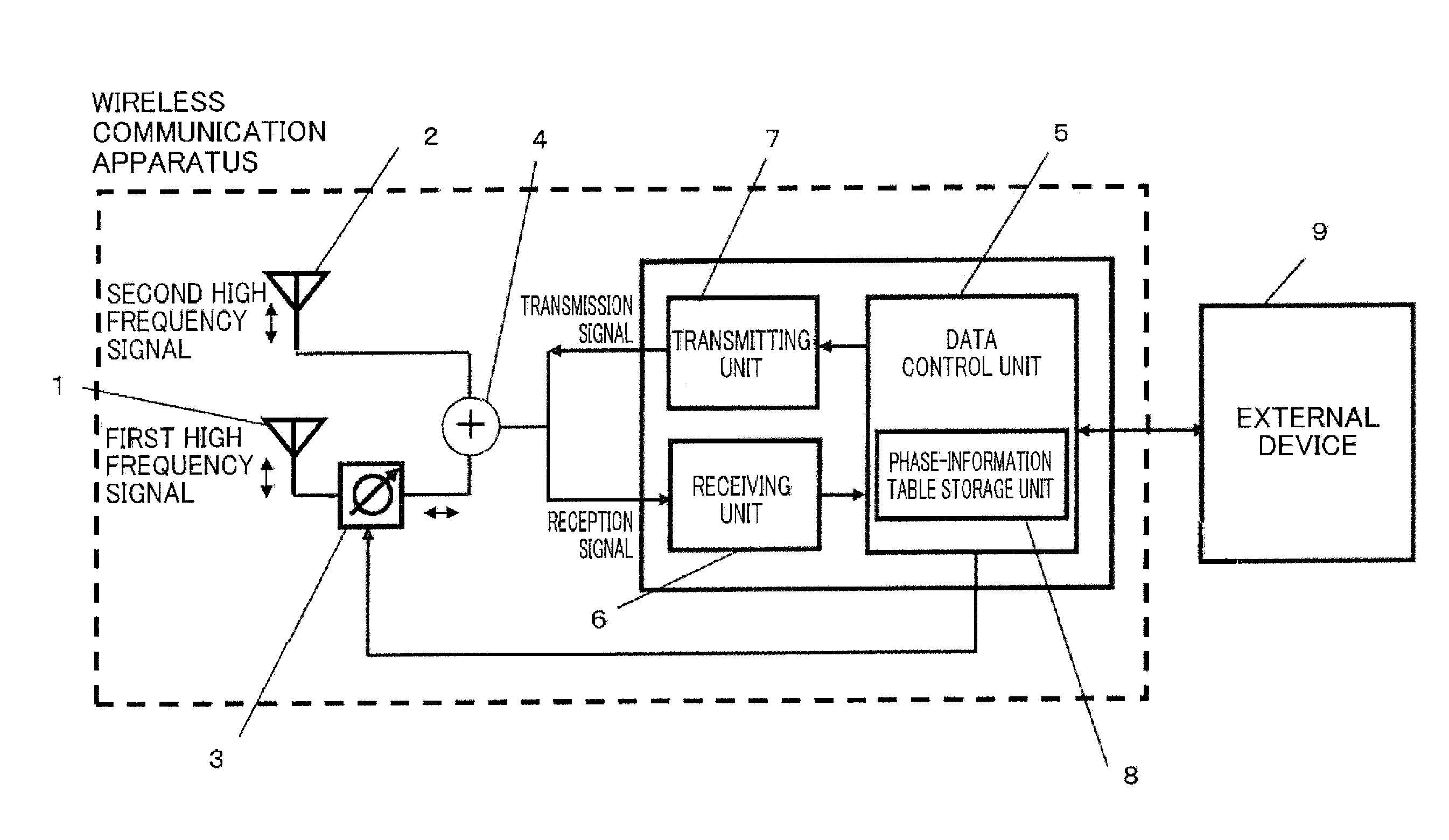
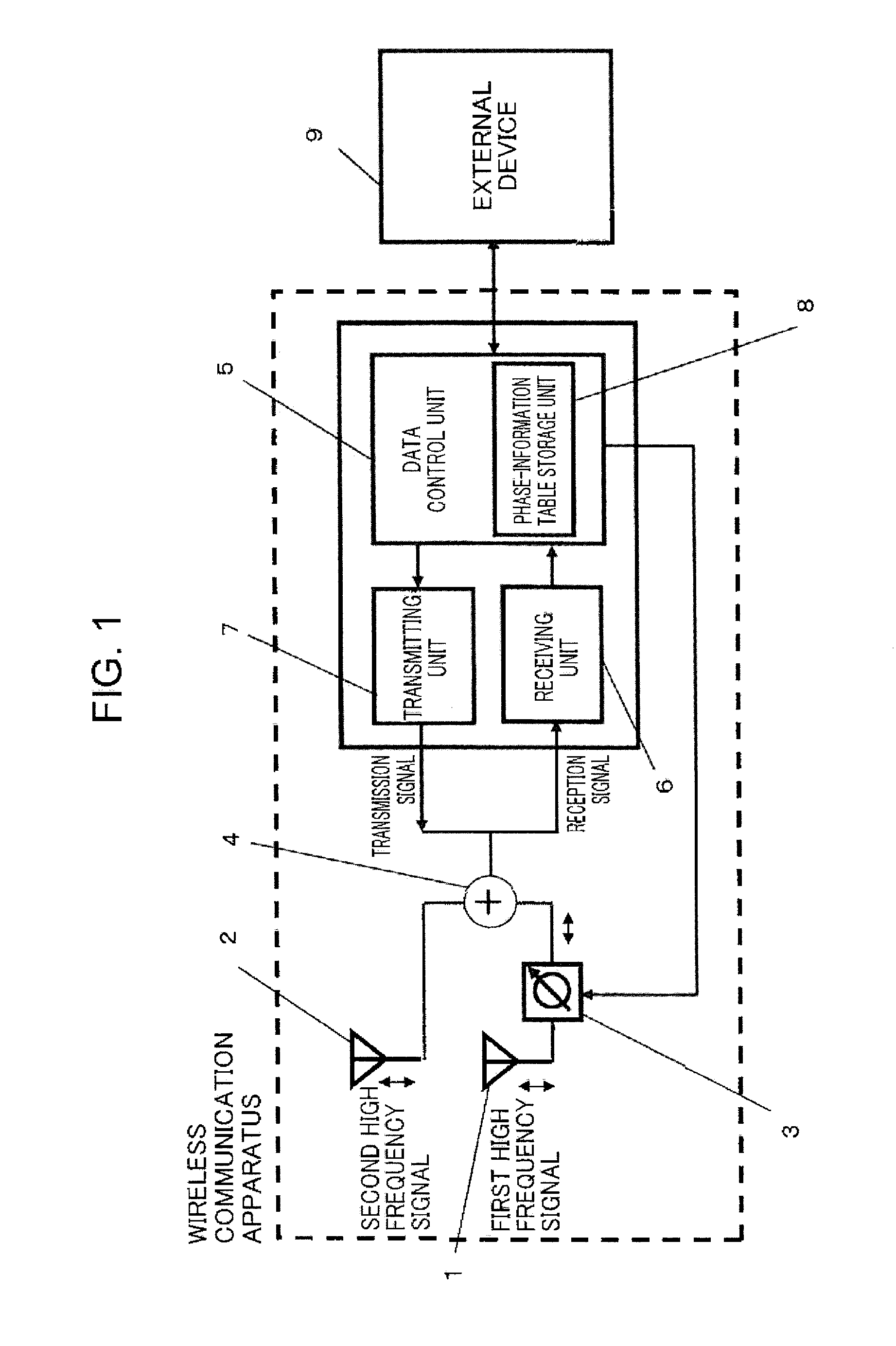
[0035]FIG. 1 is a block diagram showing an example of a configuration of a wireless communication apparatus according to Embodiment 1. As shown in FIG. 1, the wireless communication apparatus includes a first antenna 1, a second antenna 2, a variable phase shifting unit 3, a combining unit 4, a data control unit 5, a transmitting unit 7, and a receiving unit 6. In a reception state, a high frequency signal that has been received by the first antenna 1 is input to the variable phase shifting unit 3, and the high frequency signal from the variable phase shifting unit 3 is input to the combining unit 4 as a first high frequency signal.

[0036]The high frequency signal that has been received by the second antenna 2 is input to the combining unit 4 as a second high frequency signal. Then, the combining unit 4 adds and combines the first high frequency signal and the second high frequency signal, and inputs a result of the addition and combining to the receiving unit 6 as a reception signal...


PUM


Abstract

A wireless communication apparatus includes: a first antenna; a second antenna; a variable phase shifting unit that changes a phase of a high frequency signal to be received or transmitted via the first antenna and the second antenna; and a phase-information table storage unit that stores a phase information table in which phase information is associated with each of a plurality of communication terminals as communication partners. When communicating with one communication terminal out of the plurality of communication terminals via the first antenna and the second antenna, the variable phase shifting unit changes a phase of a high frequency signal on the basis of phase information stored in the phase information table in association with the one communication terminal.

Description

TECHNICAL FIELD[0001]The present invention relates to a wireless communication apparatus that performs wireless communications by using electric waves. Particularly, the invention relates to communications between wireless communication apparatuses that are fixedly installed under the environment where electric wave propagation multipaths are present.BACKGROUND ART[0002]In recent years, the use of a wireless LAN operating at 2.4 GHz or 5 GHz has become more prevalent. Further, interest has been growing in, for example, a household electrical appliance home-network for performing mutual communications between household electrical appliances by using a small electric power wireless of a 400 MHz band or a 900 MHz band.[0003]In the household electrical appliance home-network, household electrical appliances capable of performing wireless communications are relocated only a limited number of times. Further, in many cases, such household electrical appliances capable of performing wireles...

Claims


Application Information

Patent Timeline
IPC IPC(8): H04W24/02
CPCH04W24/02H04B7/024H04B7/084H04B7/0682
Inventor MORIMOTO, SHIGERU
Owner PANASONIC INTELLECTUAL PROPERTY MANAGEMENT CO LTD
Features
  • Generate Ideas
  • Intellectual Property
  • Life Sciences
  • Materials
  • Tech Scout
  • Unparalleled Data Quality
  • Higher Quality Content
  • 60% Fewer Hallucinations
Learn More