
Speed Adjustment Method and Device for Mountain Climbing Machine without External Power

a technology of speed adjustment and mountain climbing machine, which is applied in the direction of machines/engines, muscle energy, gymnastics, etc., can solve the problems of inability to the speed of the mechanical type treadmill cannot be controlled and programmed electronically, and the trainer cannot control or customize the constant speed of the mountain climbing machine. achieve the effect of effective enhancement of the training effect of the trainer and low power consumption

Active Publication Date: 2015-07-30
SHAN DONG HUIKANG SPORT EQUIP
View PDF3 Cites 2 Cited by
  • Summary
  • Abstract
  • Description
  • Claims
  • Application Information

AI Technical Summary

Benefits of technology

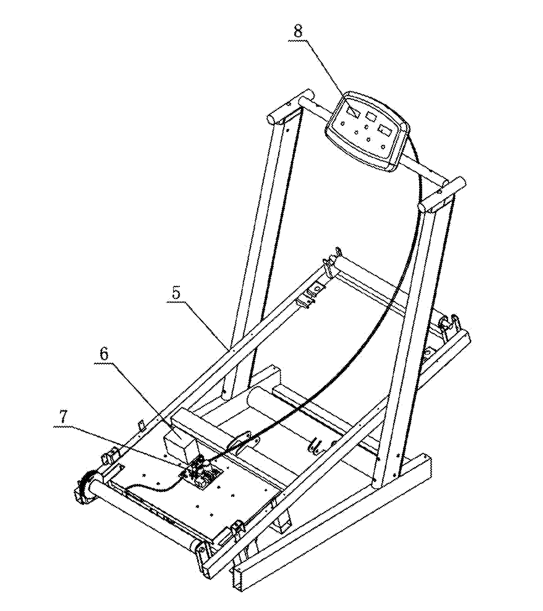
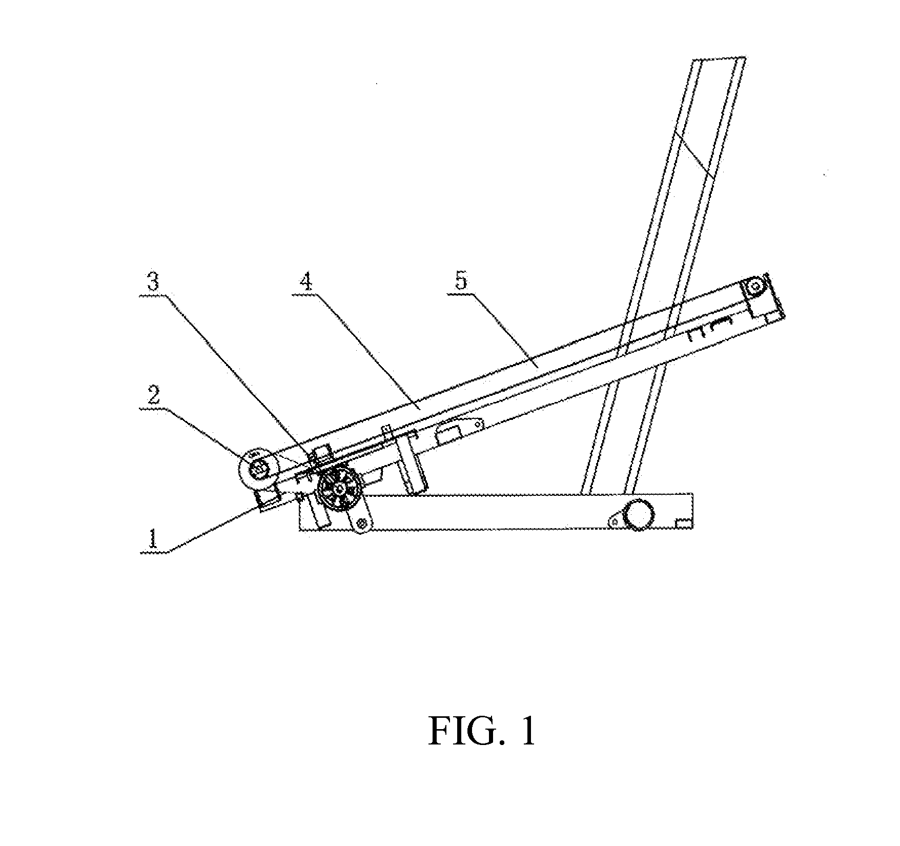
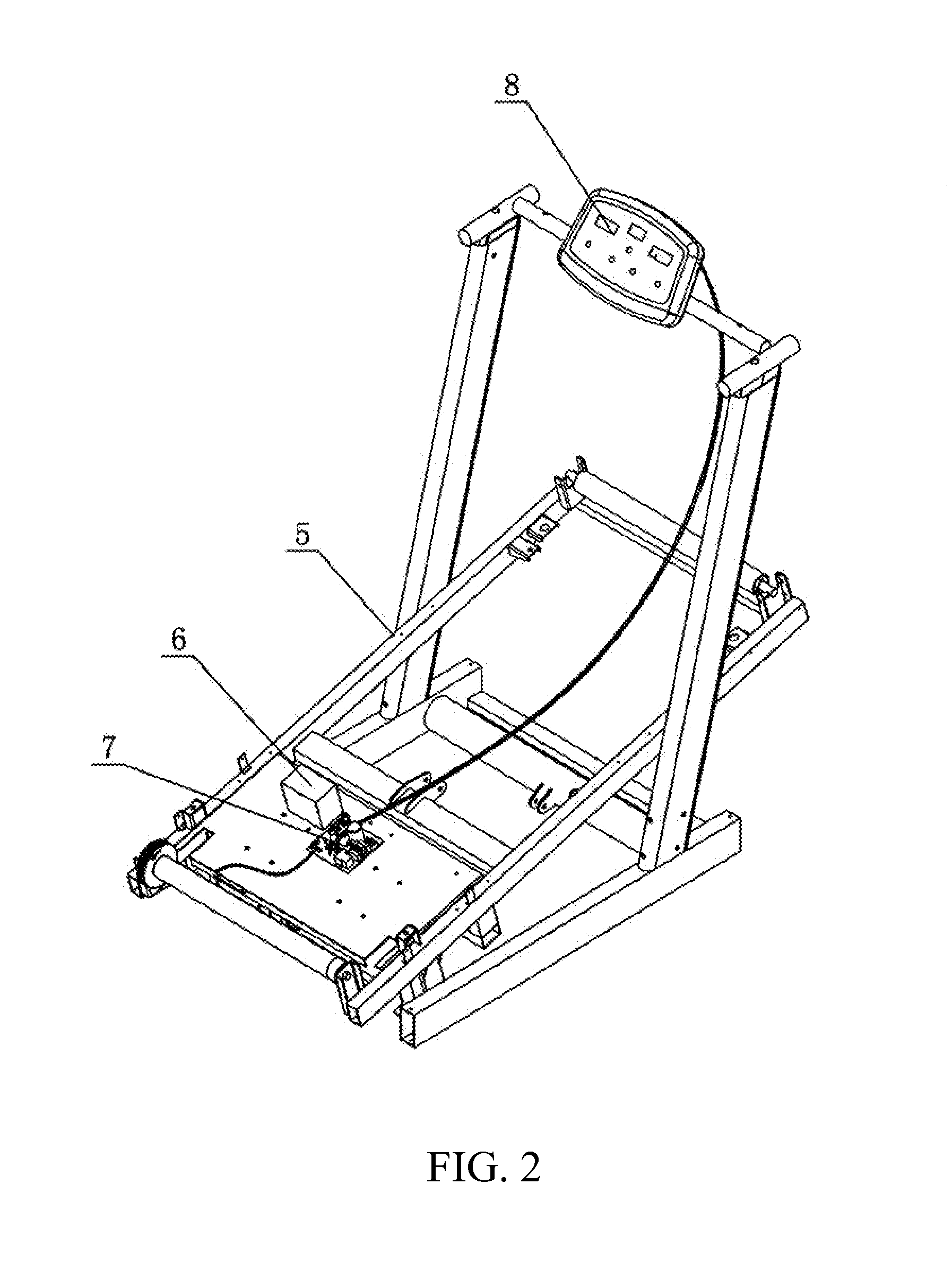
This invention is a solution for a treadmill with adjustable speed, which helps the trainer improve their training more effectively. It has low power consumption, does not require an external power source, and is flexible and applicable in various situations. The running belt of the treadmill is operated by the gravity of the trainer, saving energy and providing good fitness effects. The trainer can adjust the speed of the belt based on their physical conditions. The invention includes a generator to provide resistance force to the rollers, allowing for speed adjustment of the belt. The supporting base of the treadmill can be adjusted to different fitness requirements.

Problems solved by technology

In other words, the speed of the mechanical type treadmill cannot be controlled and programmed electronically.
Therefore, the result of using the mechanical type treadmill for the trainer cannot be optimized without the customized program.
As a result, the trainer cannot control or customize the constant speed of the mountain climbing machine.
Therefore, it is a high electrical power consumption machine comparing with the mechanical type treadmill.

Method used


Image

  • Speed Adjustment Method and Device for Mountain Climbing Machine without External Power
  • Speed Adjustment Method and Device for Mountain Climbing Machine without External Power
  • Speed Adjustment Method and Device for Mountain Climbing Machine without External Power

Examples


embodiment 2

[0049]As shown in FIG. 4, a control circuit according to a second preferred embodiment of the present invention is illustrated, wherein the control circuit comprises the signal-chip module is connected to the first driving module, wherein the driving signal is generated from the signal-chip module and is sent to the first driving module. The first driving module is operatively linked to the electronic loading module, wherein the strength of the electronic loading module is able to be controlled by the first driving module. The electronic loading module is operatively linked to the generator, wherein an electric power generated from the generator is completely consumed through the electronic loading module. The voltage and current detecting module is operatively linked to the electronic loading module, the generator, and the signal-chip module respectively, wherein the voltage and current detecting module is arranged to detect voltage and current signals of the generator, the electro...

embodiment 3

[0052]As shown in FIG. 5, a control circuit according to a third preferred embodiment of the present invention is illustrated, wherein the control circuit comprises the single-chip module operatively linked to the second driving module, wherein the driving signals are sent to the second driving module by the single-chip module. The second driving module is operatively linked to the charge-control module, wherein the output of the second driving module is able to control the strength of the charging current which is sent from the charge-control module to the rechargeable battery module for charging the rechargeable battery module. The charge-control module is operatively linked to the generator, wherein the electric power generated from the generator is transmitted to the replaceable battery module through the charge-control module. The voltage and current detecting module is operatively linked to the electronic loading module, the charge control module, the generator, and the single...

embodiment 4

[0055]As shown in FIG. 6 and FIG. 8, a control circuit according to a fourth preferred embodiment of the present invention illustrates a modification of the first embodiment, wherein the control circuit further comprises a rotational speed sensor operatively linked to the signal-chip module, which is provided at a shaft of the generator. The fourth embodiment of the present invention has the same component of the first preferred embodiment, wherein the rotational speed sensor is an additional component in the fourth embodiment.

[0056]According to the fourth embodiment of the present invention, the rotational speed of the shaft of the generator is able to be detected by the signal-chip module through the rotational speed sensor.

[0057]According to the fourth embodiment of the present invention, the rotational speed sensor is a Honeywell single-pole switch AH AH3144E. The Honeywell single-pole switch has a magnetic working valve value (Bop). If the magnetic density of the Honeywell sing...


PUM


Abstract

A mountain climbing machine, which does not require connecting with an external electrical power source, includes a running belt, front and rear rollers, and a generator operatively linked to one of the front and rear rollers for generating electrical power when the running belt is running, wherein a rotational speed of said generator is controlled by a consumption of the electrical power generated from the running belt so as to provide a resistance force at one of the front and rear rollers to maintain the running belt at a constant speed without connecting to the external electrical power source.

Description

NOTICE OF COPYRIGHT[0001]A portion of the disclosure of this patent document contains material which is subject to copyright protection. The copyright owner has no objection to any reproduction by anyone of the patent disclosure, as it appears in the United States Patent and Trademark Office patent files or records, but otherwise reserves all copyright rights whatsoever.BACKGROUND OF THE PRESENT INVENTION[0002]1. Field of Invention[0003]The present invention relates to an aerobic fitness equipment, and more particular to a speed adjustment method and device for a mountain climbing machine.[0004]2. Description of Related Arts[0005]There are two types of existing treadmills, i.e. a mechanical type and an electric type. Accordingly, the mechanical type treadmill is an active type treadmill without using an external electrical power source. The speed of the mechanical type treadmill is determined by the running speed of the trainer, and the change of the speed of the mechanical type tre...

Claims


Application Information

Patent Timeline
Patent Type & Authority Applications(United States)
IPC IPC(8): A63B24/00A63B22/02
CPCA63B22/02A63B24/0087A63B21/0054A63B21/068A63B22/0015A63B22/0023A63B22/0228A63B22/0242A63B22/025A63B71/0619A63B2022/002A63B2024/0065A63B2024/0093A63B2220/34A63B2220/36A63B2220/44A63B2220/803A63B2220/805A63B2225/15F03G5/025
Inventor LI, JUN
Owner SHAN DONG HUIKANG SPORT EQUIP
Learn More