
Electric compressor

Inactive Publication Date: 2015-07-30
TOYOTA IND CORP
View PDF12 Cites 5 Cited by
  • Summary
  • Abstract
  • Description
  • Claims
  • Application Information

AI Technical Summary

Benefits of technology

The invention is an electric compressor that can appropriately start a motor based on the condition of the compressing unit. It includes an AC motor and an inverter apparatus that controls the motor. The inverter apparatus measures the time it takes for the motor to stop and start, and calculates a target acceleration for the motor to achieve the desired load on the compressing unit. By controlling the switching circuit, the motor is started with the target acceleration. This results in a more efficient and effective starting of the motor for the electric compressor.

Problems solved by technology

The technique disclosed in Japanese Patent Laying-Open No. 2005-137069, however, is a start scheme applied to the case where a start of the DC brushless motor for a compressor fails, and does not give consideration to the condition of the compressor from the time the motor is stopped to the time the motor is restarted.

Method used


Image

  • Electric compressor
  • Electric compressor
  • Electric compressor

Examples


Embodiment Construction

[0017]The following describes the present embodiment in detail with reference to figures. It should be noted that the same or corresponding portions in the figures are given the same reference characters and explanations thereof are not repeated.

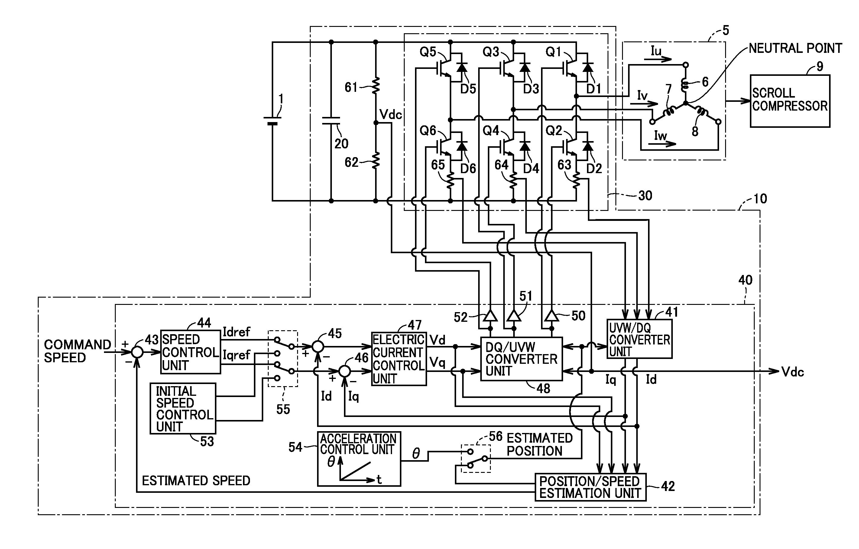
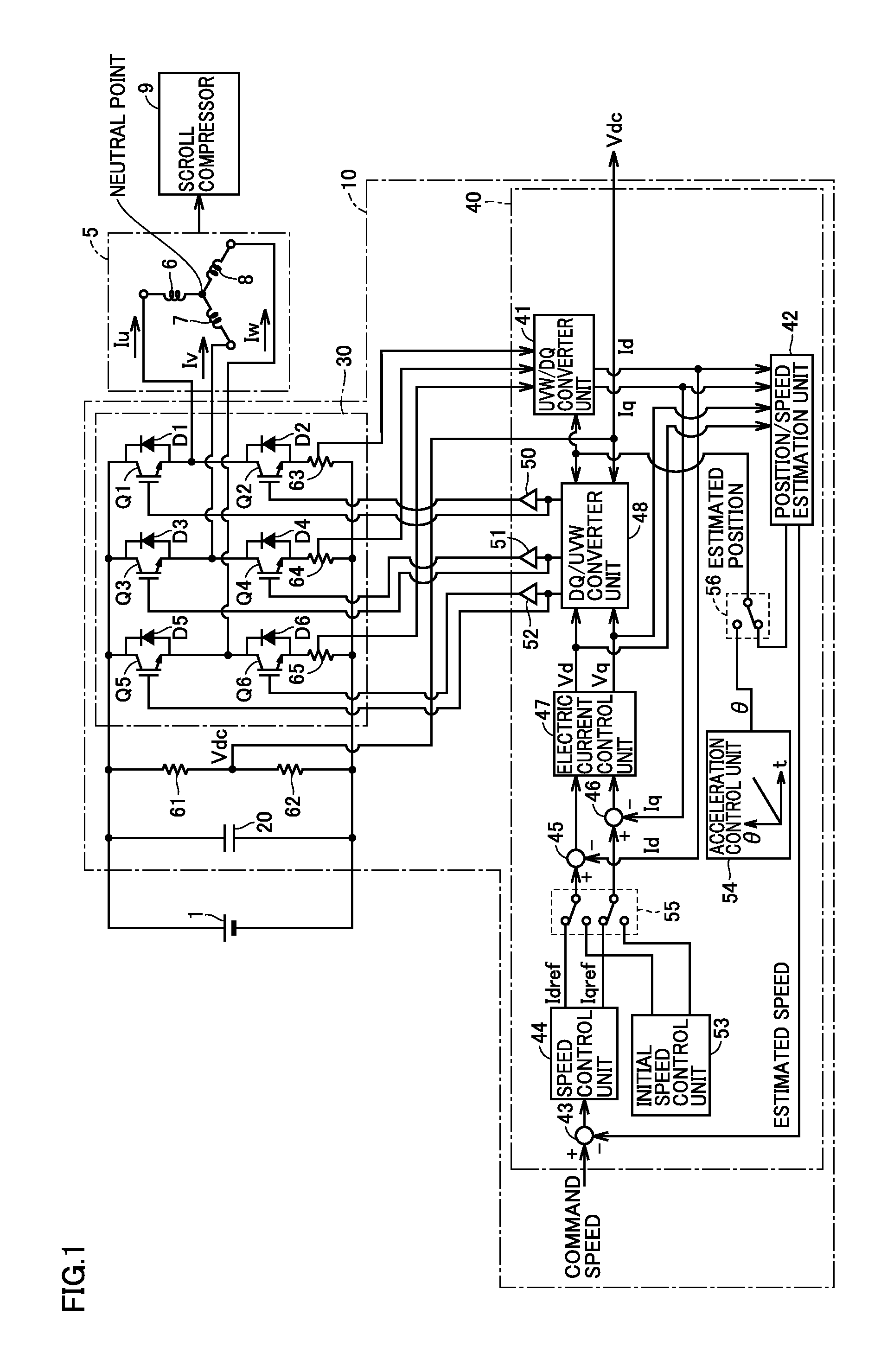
[0018]FIG. 1 is a circuit diagram showing a configuration of an electric compressor according to the present embodiment. Referring to FIG. 1, the electric compressor includes an AC motor 5, an inverter apparatus 10, a scroll compressor (compressing unit) 9 driven by the AC motor 5.

[0019]The inverter apparatus 10 receives an input of power from a high voltage battery 1 which is a DC power supply and controls driving of the AC motor 5. The AC motor 5 is a three-phase synchronous motor which includes a rotor having a permanent magnet and a stator where respective phase coils 6, 7, and 8 are wound. For example, the AC motor 5 is used as a motor for an air conditioner of a vehicle (a motor for an air conditioner compressor).

[0020]The inverter app...


PUM


Abstract

An electric compressor capable of appropriately starting a motor depending on a condition of a compressing unit is provided. The electric compressor includes: an AC motor including a rotor having a permanent magnet and a stator where a multi-phase coil is wound, and driving a scroll compressor; and an inverter apparatus controlling the AC motor. The inverter apparatus includes: a switching circuit supplying the AC motor with current; and a motor control unit controlling the switching circuit. The motor control unit: measures an elapsed time from a stop to a start of the AC motor for controlling the switching circuit depending on a load on the scroll compressor; calculates a target acceleration of the rotor followed when starting the AC motor, based on the measured elapsed time; and controls the switching circuit so that the rotor is started with the target acceleration.

Description

[0001]This nonprovisional application is based on Japanese Patent Application No. 2014-012281 filed on Jan. 27, 2014 with the Japan Patent Office, the entire contents of which are hereby incorporated by reference.BACKGROUND OF THE INVENTION[0002]1. Field of the Invention[0003]The present disclosure relates to an electric compressor.[0004]2. Description of the Background Art[0005]In recent years, a motor in which a permanent magnet is placed in a rotor has been used widely for an air conditioner or a vehicle such as hybrid vehicle, electric vehicle, or fuel cell vehicle. As a start scheme for starting such a motor, the following technique has been proposed.[0006]For example, Japanese Patent Laying-Open No. 2005-137069 discloses that a DC brushless motor for a compressor is started in the following way. When a start fails, start parameters for the DC brushless motor are changed to data stored in advance and restarts are successively done. When the number of times this start has failed...

Claims


Application Information

Patent Timeline
IPC IPC(8): F04D25/06H02P23/00
CPCH02P23/0063F04D25/06F04C23/008F04C28/06F04C18/0207F04C2240/403F04C2270/06H02P21/18H02P23/20
Inventor NAGATA, YOSHIKI
Owner TOYOTA IND CORP
Learn More