Immunoassay rapid diagnostic test universal analysis device, system, method and computer readable medium

a technology of rapid diagnostic test and analysis device, which is applied in the direction of chemical methods analysis, material testing goods, instruments, etc., can solve the problems of inconvenient visual interpretation by end users, inability of devices to read more than one type of products, and human interferen

Inactive Publication Date: 2015-07-30
FIO CORP
View PDF4 Cites 8 Cited by
  • Summary
  • Abstract
  • Description
  • Claims
  • Application Information

AI Technical Summary

Benefits of technology

[0058]According to one aspect of the present invention, the device, system and / or method may preferably, but need not necessarily, include an electronic board, a processor (e.g., a microprocessor), image analysis and / or processing software, a light chamber, one or more white (cassette recognition, reflection) LEDs, one or more color (emission) LEDs and / or ultraviolet (“UV”) LEDs, an optical filter, and / or a color camera. Preferably, the optical filter may be an optical band pass filter and / or an optical long pass filter. Preferably, the optical filter may be mounted on a sliding switch and / or on a rotatable mechanism, and / or it may be moved towards and / or away from the front of the camera. Preferably, the LEDs may be illuminated (i.e., on) to permit the camera to take a picture, and may preferably just illuminate the light chamber when the camera is taking a picture. The processor and / or controlling electronics may control whether one or more of the LEDs is on or off. The device, system and / or method may preferably enable one or more lateral flow cassettes to be received for recognition and analysis. The microprocessor may preferably be adapted with image processing software for analysis of one or more images of the lateral flow cassettes.
[0059]According to one aspect of the present invention, for reading reflection signal type of tests (e.g., colloidal gold and / or colored latex bead types of tests), the white LEDs may preferably be on. [References herein to use of the invention with colloidal gold tests and / or colored latex bead tests may be considered, more generally, as references to its use (if and when appropriate) with reflection signal tests, with any changes which may be necessary and / or appropriate for such use.] In such circumstances, the color and / or UV LEDs may preferably be off. The optical filter may preferably be switched away from the color camera. Preferably, the color camera may take an image of the entire cassette, preferably including the plastic case and / or membrane area.
[0060]According to one aspect of the present invention, the image taken by the camera may preferably be analyzed by the image analysis and / or processing software in the microprocessor. [Each reference herein to image analysis software and / or to image processing software may be considered as a reference (if and when appropriate) to the other, to imaging software, and / or to software more generally, with any changes which may be necessary and / or appropriate in such instance.] The function of the image analysis software may preferably include: (1) cassette recognition, preferably with reference to cassette features (such as for example size, aspect ratio, color, shape, letters, etc.) and / or so as to provide a user with information concerning the cassette manufacturer, disease to be tested, etc.; (2) membrane region identification; (3) measurement of the intensity of the test line and / or control line in the membrane region and / or area; and / or (4) presenting diagnostic results according to one or more cut-off values, preferably as pre-set in the software.
[0061]The image processing software may preferably assess one or more images to determine and / or present the user cassette type and the diagnostic results to a user of the device, system and / or method according to the invention.
[0062]According to one aspect of the present invention, for reading emission signal type of tests (e.g., fluorescent lateral flow cassette tests), two or more images may preferably but need not necessarily be taken for each test. [References herein to use of the invention with fluorescent signal tests may be considered, more generally, as references to its use (if and when appropriate) with emission signal tests, with any changes which may be necessary and / or appropriate for such use.] In such circumstances, the first image may preferably be an image of the cassette as taken with the white LED on, and the color LEDs off, and with the optical filter (e.g., an optical band pass filter) moved away from the camera. [Each reference herein to an optical band pass filter and / or to an optical long pass filter may be considered as a reference (if and when appropriate) to optical filters, more generally, and / or to another specific type of optical filter, with any changes which may be necessary and / or appropriate for such filter.] Preferably, after the first image, a further image (e.g., the second image) may be a fluorescent signal image of the membrane region, preferably with the color LEDs on and / or the white LEDs off, and preferably with the optical filter (e.g., the optical band pass filter) in front of the camera. Preferably, for emission signal tests, there may be no line visible in the membrane area in the first image because, preferably, the color and / or UV LEDs (which may be required for fluorescent lateral flow images) may be off. [Each reference herein to color LEDs and / or to UV LEDs may be considered as a reference (if and when appropriate) to the other and / or to non-white LEDs, more generally, with any changes which may be necessary and / or appropriate for such LEDs.] The first image may preferably enable software according to the invention to perform cassette recognition. Preferably, the fluorescent control line and / or test signal line may be present and / or visible in the second image. [According to one aspect of the present invention, the fluorescent control line and / or test signal line may be rendered visible by the optical filter.] The image processing software may preferably combine and / or assess the two or more images to determine and / or present the user cassette type and the diagnostic results to a user of the device, system and / or method according to the invention.
[0063]Other advantages, features and characteristics of the present invention, as well as methods of operation and functions of the related elements of the device, system, method, and computer readable medium and the combination of steps, parts and economies of manufacture, will become more apparent upon consideration of the following detailed description and the appended claims with reference to the accompanying drawings, the latter of which are briefly described hereinbelow.

Problems solved by technology

Such visual interpretation by end users may have been subject to inconsistency and / or human interference.
It may have been almost impossible for a device to read more than one type of these products.

Method used


Image

  • Immunoassay rapid diagnostic test universal analysis device, system, method and computer readable medium
  • Immunoassay rapid diagnostic test universal analysis device, system, method and computer readable medium
  • Immunoassay rapid diagnostic test universal analysis device, system, method and computer readable medium

Examples


Embodiment Construction

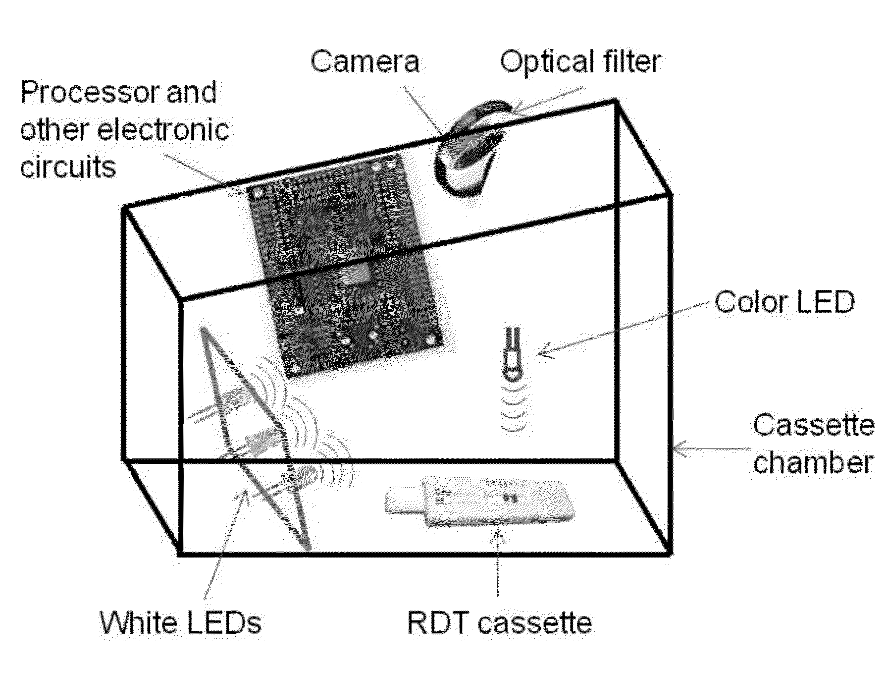
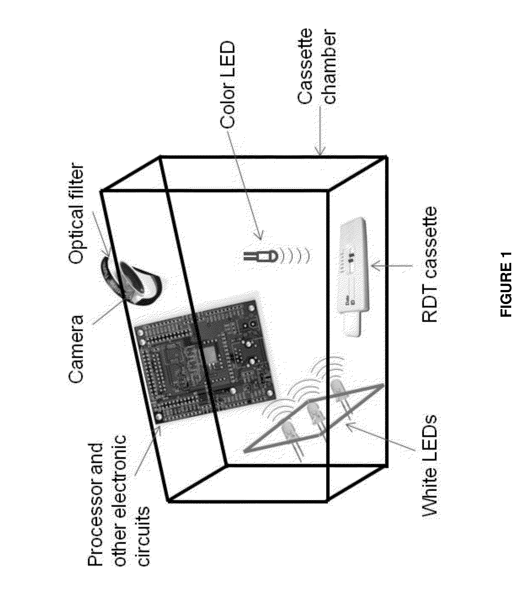
[0071]Preferred embodiments of the device, system, method, and computer readable medium according to the invention are alternately herein referred to, collectively and / or individually, as the universal lateral flow reader, device, system, method and / or computer readable medium (or simply as the reader, device system, method and / or computer readable medium). References to one or more of the reader, device, system, method and / or computer readable medium may, if and as appropriate, be understood by persons having ordinary skill in the art to apply, mutatis mutandis, to the others.

[0072]Persons skilled in the art will appreciate that although some of the components, relations, functionalities and applications of the reader, device, system, method and computer readable medium are not specifically referenced or described in conjunction with each other, they may be used or adapted for use in association therewith. The reader, device, system, method and computer readable medium described he...


PUM

PropertyMeasurementUnit
cutting edge wavelengthaaaaaaaaaa
reflectionaaaaaaaaaa

Abstract

A device, system, method, and computer readable medium is provided for universal analysis of immunoassay rapid diagnostic tests. They permit different tests, from varied manufacturers, to be read even though such tests may be associated with reflection and/or emission types of signals. The device, system, method, and computer readable medium use one or more rapid diagnostic test databases, including information on products commercially available on the market and on customized rapid tests. The device, system, method, and computer readable medium identify the type of test to be analyzed by matching it with the test database(s). They capture a corresponding reflection and/or emission signal from the test, as appropriate. The device, system, method, and computer readable medium may transform the signal to an image, or vice-versa, and/or analyze the image to interpret the test result.

Description

FIELD OF THE INVENTION[0001]The present invention relates generally to an rapid diagnostic test analysis device and method, and more particularly to an immunoassay rapid diagnostic test universal analysis device, system, method and computer readable medium.BACKGROUND OF THE INVENTION[0002]In the prior art, the rapid immunoassay diagnostic test may have achieved great commercial application in many fields—potentially including, for example, in association with pregnancy tests, infectious disease tests, oncology tests, cardiovascular disease tests, animal health tests, and / or tests related to foods and the environment, etc. One of the most successful examples may be all kinds of lateral flow immunoassay tests.[0003]Usually, lateral flow types of rapid tests may have been visually interpreted by end users. Such visual interpretation by end users may have been subject to inconsistency and / or human interference. There may be a trend to using devices to analyze the results of such tests. ...

Claims


Application Information

Patent Timeline
Patent Type & Authority Applications(United States)
IPC IPC(8): G01N33/53G01N33/543G01N21/64
CPCG01N33/5302G01N2201/062G01N33/54366G01N21/6456G01N21/64G01N33/48
Inventor XIANG, QINGLEE, JEONGJIN
Owner FIO CORP
Why Eureka
Try Eureka