Service data record system and POS system with the same

a service data and record system technology, applied in the field of service data record systems, can solve the problems of difficult repair process, difficult for users or service engineers to readily identify the failed component(s) among the large amount of components, and takes a long time for trouble shooting

Inactive Publication Date: 2015-07-30
FLYTECH TECH
View PDF1 Cites 11 Cited by
  • Summary
  • Abstract
  • Description
  • Claims
  • Application Information

AI Technical Summary

Benefits of technology

[0012]The present invention provides a service data record system for an electronic device and a POS system with the service data record system. By the service data record system, the pre-designate event of the electron...

Problems solved by technology

However, it leads to some difficulties during the repair process.
For example, if the POS device is abnormal or unable to be booted while being used, it is hard for a user or a service engineer to readily identify the failed component(s) among the large amount of components.
Actually, it takes much time for trouble shooting.
Furthermore, when the service engineer analyzes the POS device 1, it is hard for the service engineer to accurately find out the reason why the component fails only according to the factory data such as the model type, the specification, the manufactured date, etc.
However, the failure detection device disclosed in this patent still has some drawbacks as follows.
Firstly, the BIOS is only suitable for detecting the failed hardware component related to the motherboard.
Whereas, the breakdown status of the display, the hard disk or the peripheral device and the usage information cannot be obtained through the BIOS.
Secondly, if the electronic device is abnormal, the user or the service engineer can only realize which hardware component fails but cannot realize the information about the failed hardware component (e.g. the usage time, the use frequency or the failure rate) through the display module.
Under this circumstance, the service engineer cannot effectively repai...

Method used


Image

  • Service data record system and POS system with the same
  • Service data record system and POS system with the same
  • Service data record system and POS system with the same

Examples


Embodiment Construction

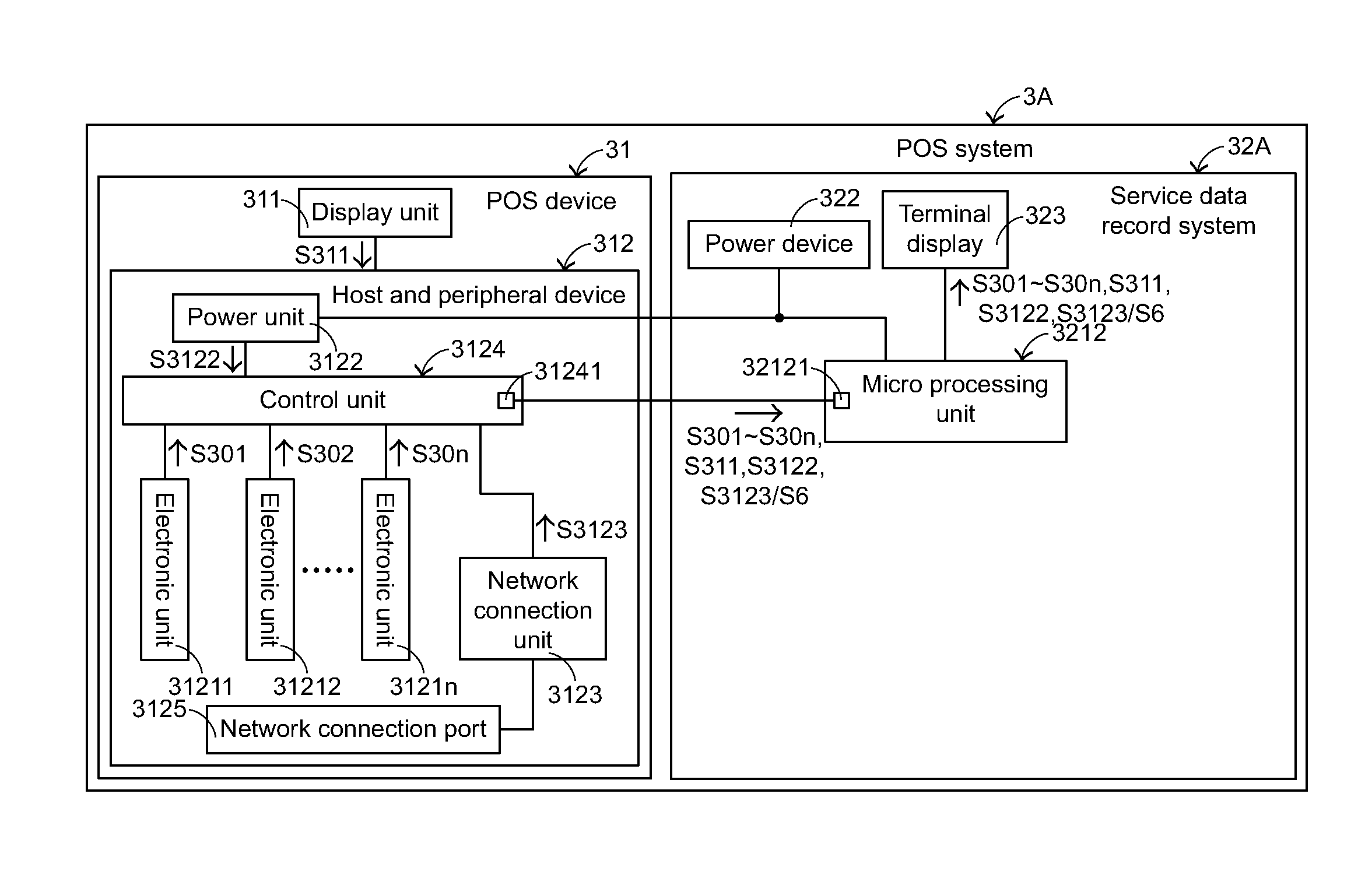
[0041]The present invention provides a service data record system (also referred as a SDR system). The service data record system may be applied to various kinds of electronic devices. The service data record system may be used for displaying various designated event data of the electronic device at the user side (i.e. terminal) in order to allow a user to conduct routine maintenance or allow a service engineer to conduct breakdown maintenance and reliability analysis. The details of the designated event data will be illustrated later. In the following embodiments, a POS device will be illustrated as the example of the electronic device. It is noted that the type of the electronic device may be varied according to practical requirements.

[0042]FIG. 3 is a schematic block diagram illustrating a POS system according to a first embodiment of the present invention. As shown in FIG. 3, the POS system 3A comprises a POS device 31 and a service data record system 32A. The POS device 31 comp...


PUM


Abstract

A service data record system and a POS system with the service data record system are provided. The service data record system is used to display a data of an electronic device. The electronic device includes at least one electronic unit and a power unit. The service data record system includes a power device, a terminal display, a remote monitoring interface and a micro processing unit. By the micro processing unit, the electronic data set of the electronic unit may be displayed on the terminal display or transmitted to a remote monitoring device. Moreover, the pre-designate event of the electronic device may be displayed on the terminal display. According to the pre-designate event, it is convenient for a service engineer to conduct breakdown maintenance of the electronic device.

Description

FIELD OF THE INVENTION[0001]The present invention relates to a service data record system, and more particularly relates to a service data record system for an electronic device and a POS system with the service data record system.BACKGROUND OF THE INVENTION[0002]A point of sale device, also referred as a point of service device or a POS device, is a widely used electronic device in retail industry nowadays, and is mainly used for managing products and the customer information. Generally, the POS device is usually installed on a cashier desk in a convenience store, a shop or a supermarket for displaying the information and the sum of price of merchandise purchased by consumers. Consequently, it is convenient for a cashier to operate the counting task and avoid errors that may be generated in the checkout process.[0003]Please refer to FIG. 1, which is a schematic perspective view of a conventional POS device. The POS device 1 comprises a screen body 11, a bracket base 12 and a host c...

Claims


Application Information

Patent Timeline
IPC IPC(8): G06Q20/20
CPCG06Q20/202G06Q20/20G07G1/0018G07G1/12G07F9/026
Inventor LAM, TAI-SENGLEE, HSIAO-HUITSAI, SHUEI-JIN
Owner FLYTECH TECH
Why Eureka
Try Eureka