Supercharge Your Innovation With Domain-Expert AI Agents!

Document validating/stacking device

a document validation and document technology, applied in the field of document validation/stacking devices, can solve the problems of cam devices that cam devices may necessarily involve undesirable friction, and may require a larger cam device, so as to achieve convenient and efficient use, increase the extension length of x-linkage, and less slippage

Active Publication Date: 2015-07-30
JAPAN CASH MASCH CO LTD
View PDF2 Cites 1 Cited by
  • Summary
  • Abstract
  • Description
  • Claims
  • Application Information

AI Technical Summary

Benefits of technology

This patent describes a device that allows for a more efficient and precise movement of a component (e.g. a head) in a linear motion. The device uses a rocker to cause the head to move in a circular arc, which results in a larger movement than a device that simply moves the head radially. This allows for a longer extinction of a linkage, and it is also easier and more efficient to convert the movement of the head into the movement of the driver arm. Additionally, the head pushes the driver arm with no pressure and with almost no slippage, reducing wear and noise between the head and the driver arm.

Problems solved by technology

The security currency cassette in the first reference is disadvantageous that it must rely on the large-sized and heavy actuating fork operated by rotation of the cam to push the currency into a predetermined position of the cassette.
First, the cam may necessarily involve undesirable friction, slippage, wear and abnormal noise in a sliding boundary with a follower driven by the cam to turn rotational motion of the cam into a different motion of the follower.
In addition, the cam that drives a follower such an X-linkage, is alleged to require a lesser pressure angle formed between a pushing direction of the cam and a moving direction of the X-linkage because a greater pressure angle would disadvantageously exert a larger gouging force on contiguous X-linkage.
Accordingly, to reduce the pressure angle of the cam for good collaboration with a prior art X-linkage, the cam device disadvantageously requires utilization of a larger sized cam.

Method used


Image

  • Document validating/stacking device
  • Document validating/stacking device
  • Document validating/stacking device

Examples


first embodiment

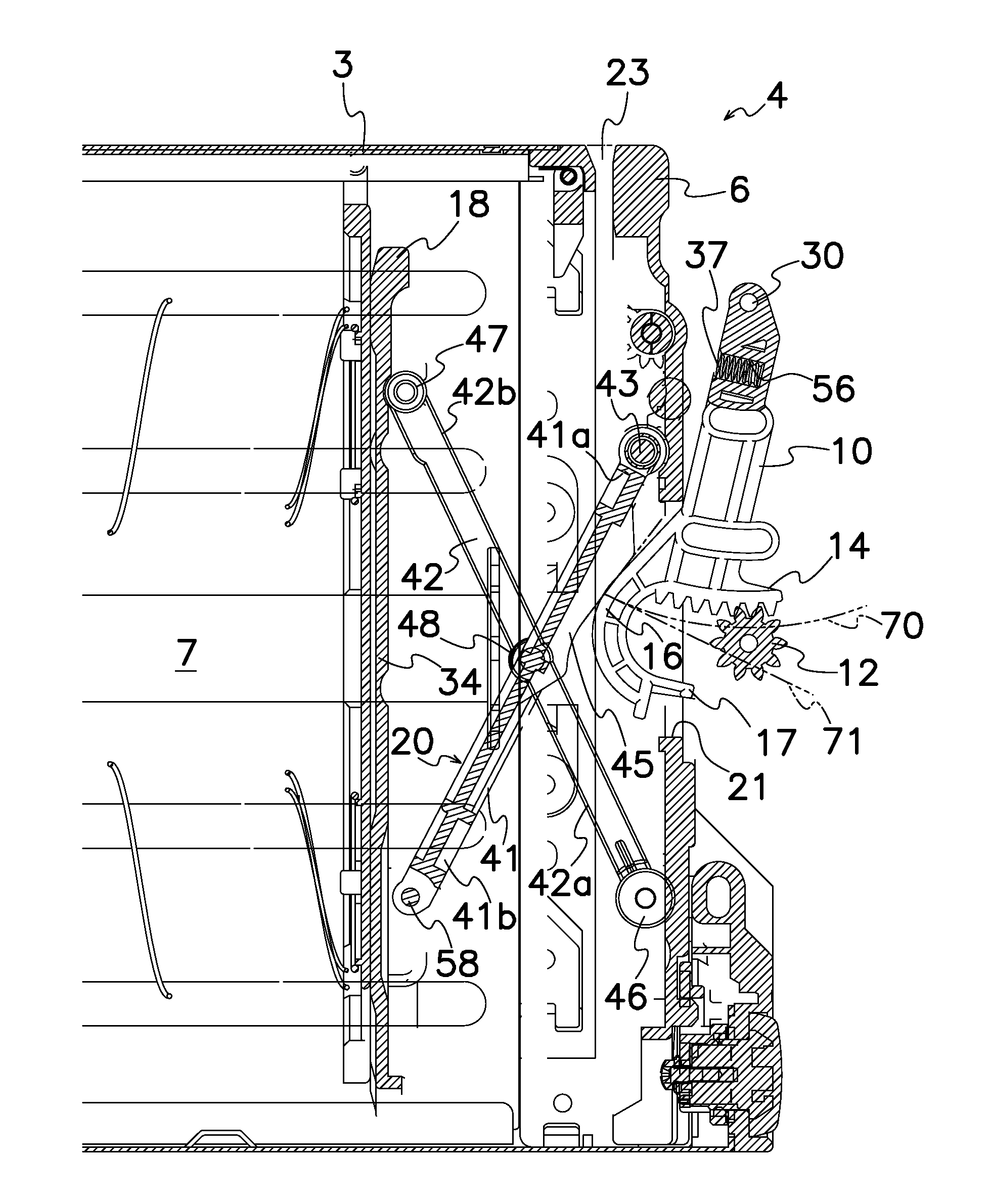
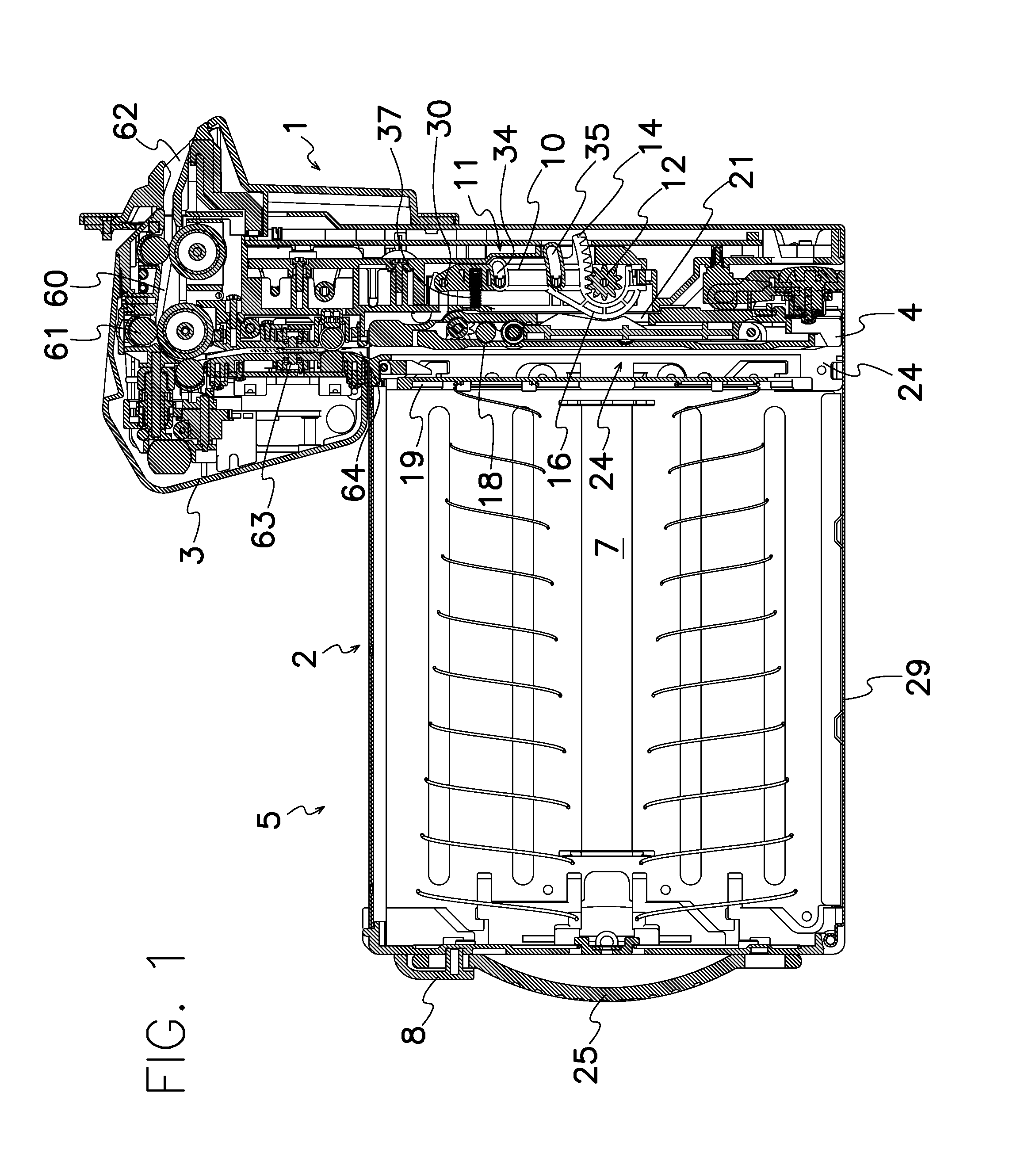
[0032]Validator 1 comprises a rocker or swing lever 10 pivotally or rotatably attached around a pivot shaft 30 and a drive device 11 for rotating or swinging rocker 10. In the invention shown in FIGS. 1 and 15, rocker 10 comprises an arm 31 rotatably mounted on pivot shaft 30, and an external sector gear 14 integrally formed in arm 31 and meshed with a pinion 12 of drive device 11. An arcuate extension 17 is also integrally formed with and protruded from arm 31 with a head 16 integrally formed on arcuate extension 17. In the shown embodiment, sector gear 14 is formed along the periphery of arm 31 for engagement with circumscribed pinion 12. Shown external sector gear 14 may be replaced with an internal sector gear formed on an inner surface of arcuate extension 17 integrated with head 16 to bring the internal sector gear into engagement with inscribed pinion.

[0033]As seen from FIG. 16, drive device 11 comprises a drive motor 13 and a deceleration device 9 arranged in substantially p...

third embodiment

[0050]FIG. 19 illustrates the invention wherein drive device 11 comprises a solenoid 15 for rotating rocker 10 in lieu of drive device 11 made up of a drive motor and a sector gear. Push-pull operation of solenoid 15 allows rocker 10 to move to extend X-linkage 20 to stow a bill into storage 7, and to retract it to return rocker 10 to the original position in collaboration with resilient forces of coiled springs 28 and spring 37.


PUM


Abstract

A document validating / stacking device is provided that has a validator 1 provided with a swingable rocker 10 formed with a head 16 and a stacker 2 detachably attached to validator 1. Stacker 2 comprises an X-linkage 20 having a driver arm 41 that is separably pushed by head 16 in the same rotational direction as head 16 swings to expand X-linkage 20, to thereby move pusher plate 18 from the initial position to the extended position and to stow the document within interim chamber 24 into storage 7.

Description

TECHNICAL FIELD[0001]This invention relates to a document validating / stacking device that has a rocker provided in a validator to have the rocker rotating and to thereby extend an X-linkage in a stacker that smoothly stows a document in an interim chamber into a storage within the stacker.BACKGROUND OF THE INVENTION[0002]U.S. Pat. No. 5,653,436 discloses a secure currency cassette that comprises a mounting chassis, a transport unit attached to the mounting chassis and a currency cassette removably attached to the mounting chassis for storing currencies sent from the transport unit. The secure currency cassette further comprises an actuating fork rotatably mounted about a pivot within the transport unit, a cam whose outer surface drives one end of the actuating fork, and a pusher plate pushed by the other end of the actuating fork. Rotation of the cam causes the actuating fork to rotate so that the other end of the actuating fork pushes and moves the pusher plate to stow a currency i...

Claims


Application Information

Patent Timeline
IPC IPC(8): G07F7/04
CPCG07F7/04B65H29/46B65H31/06B65H2701/1912G07D11/125G07D11/16G07D11/10G07D11/13G07D11/40B65H2402/30G07D9/00B65H2405/1142G07D11/12
Inventor ITO, KENICHI
Owner JAPAN CASH MASCH CO LTD
Features
  • R&D
  • Intellectual Property
  • Life Sciences
  • Materials
  • Tech Scout
  • Unparalleled Data Quality
  • Higher Quality Content
  • 60% Fewer Hallucinations
Learn More