Paper folding apparatus and image forming apparatus

Active Publication Date: 2015-08-06
KONICA MINOLTA INC
View PDF10 Cites 3 Cited by
  • Summary
  • Abstract
  • Description
  • Claims
  • Application Information

AI Technical Summary

Benefits of technology

The present invention provides a paper folding apparatus that can fold various kinds of paper adequately by forming deflection of the paper between a pair of folding rollers and guiding the deflection part of the paper to the nip part of the folding rollers. This is achieved by a pushing member that pushes the deflection part of the paper towards the nip part of the folding rollers, even if the speed to form the deflection and push the paper out is not identical. The elastic force of the elastic member reduces impact force and ensures a fixed position of the deflection part of the paper, regardless of the different formation conditions of the deflection. This results in a simple and effective apparatus for paper folding.

Problems solved by technology

However, a shape of the deflection formed at the part of the paper between the pair of folding rollers is not fixed.
Specifically, there has been a problem that a fold position of thick paper having high basis weight and high stiffness and that of thin paper having low basis weight and low stiffness are different from each other.
Thus, when the speed to push out the deflection part of the paper toward the gap between the folding rollers by the bend part of the fold position regulation member becomes higher than the speed to form the deflection of the paper, there has been the following problem.
That is, the paper is pushed by the bend part of the fold position regulation member and a position of a leading end of the paper abutted on a stopper or the like is shifted, and thus, a position of the paper guided to a nip part of the pair of folding rollers is shifted and it becomes not possible to fold the paper at an adequate position in the nip part of the folding rollers.
On the other hand, when the speed to form the deflection of the paper becomes higher than the speed to push out the deflection part of the paper toward the gap between the folding rollers by the bend part of the fold position regulation member, there has been the following problem.
That is, before the deflection part of the paper is pushed out toward the gap between the folding rollers by the bend part of the fold position regulation member, the deflection part of the paper is guided to the nip part of the folding rollers and a position of the paper guided to the nip part of the pair of folding rollers is not fixed, and thus, it becomes not possible to fold the paper at an adequate position in the nip part of the folding rollers.
However, it is very difficult to perform control, by the simultaneous circuit storing a folding form or the like as described above, to move the redirecting mechanism toward the gap between the folding rollers by controlling rotation of the cam or the like and to guide the paper, which is carried along the carrying track, to an adequate fold position toward the gap between the folding rollers.
Thus, a configuration to perform the control becomes complicated, and thus, there has been a problem that a cost is increased and an apparatus becomes large, for example.

Method used


Image

  • Paper folding apparatus and image forming apparatus
  • Paper folding apparatus and image forming apparatus
  • Paper folding apparatus and image forming apparatus

Examples


Embodiment Construction

[0031]Hereinafter, a paper folding apparatus and an image forming apparatus according to an embodiment of the present invention will be described in detail with reference to the attached drawings. However, the scope of the invention is not limited to the illustrated examples. Note that the paper folding apparatus and the image forming apparatus according to the present invention are not limited to what is described in the following embodiment and can be modified arbitrarily within the spirit and the scope thereof.

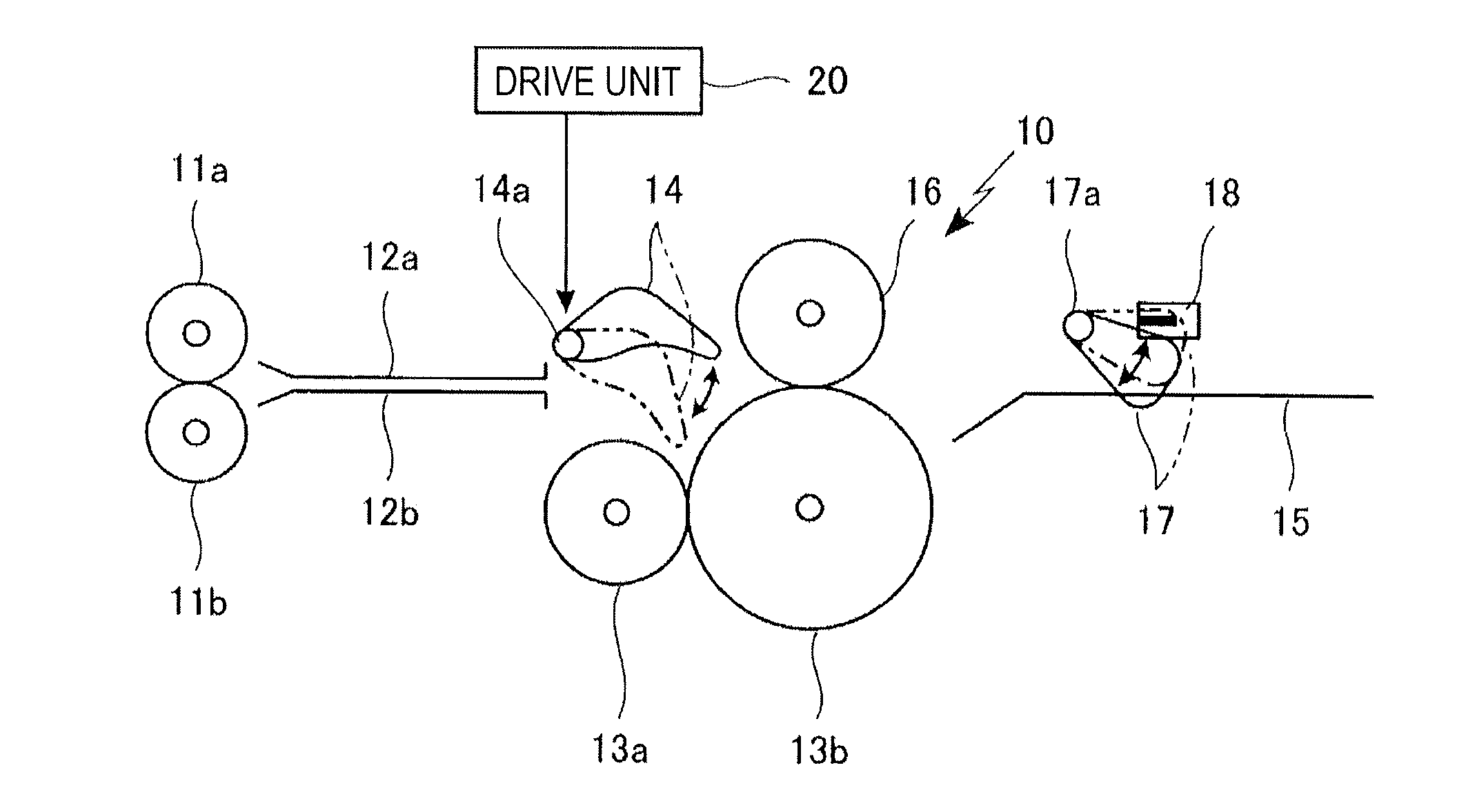
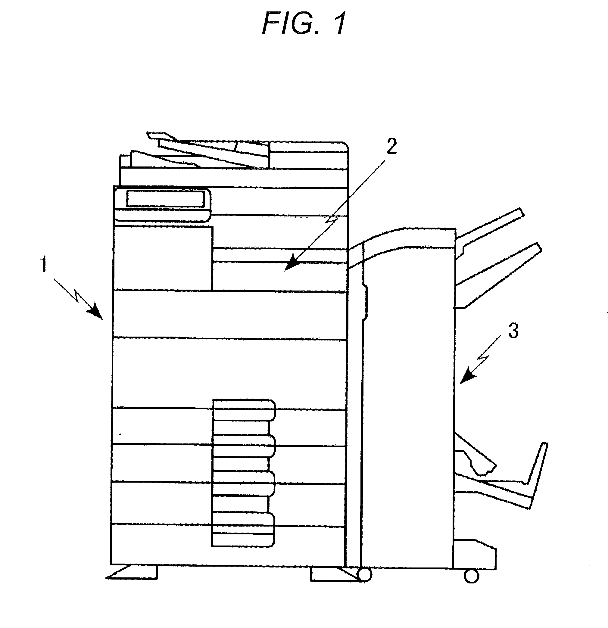
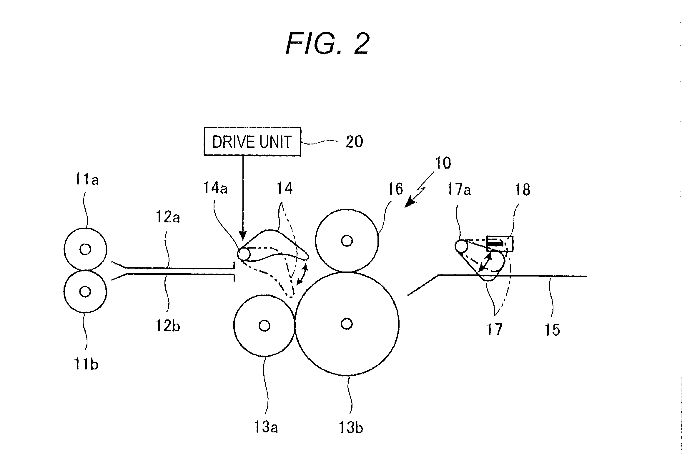
[0032]In the present embodiment, as illustrated in FIG. 1, a paper post-processing apparatus 3 is connected to an image forming apparatus 1 such as a copier via a horizontal carrying unit 2. Although not illustrated, paper on which an image is formed by the image forming apparatus 1 is fed to the paper post-processing apparatus 3 via the horizontal carrying unit 2. The paper transmitted to the paper post-processing apparatus 3 in such a manner is folded at a predetermined p...


PUM

PropertyMeasurementUnit
Forceaaaaaaaaaa
Shapeaaaaaaaaaa

Abstract

A paper folding apparatus includes: a pair of folding rollers driven in a rotational manner; a carrying roller configured to carry paper in such a manner that the paper passes near a nip part of the pair of folding rollers; a unit configured to form, near the nip part, deflection of the paper carried by the carrying roller toward the nip part; a pushing member which is configured to push the paper, which is carried by the carrying roller, toward the nip part of the folding rollers, the pushing member being provided in a manner movable from a position retracted from a carrying path of the paper toward the nip part; a drive unit configured to generate driving force to move the pushing member; and an elastic member configured to transmit the driving force from the drive unit to the pushing member.

Description

[0001]The entire disclosure of Japanese Patent Application No. 2014-020887 filed on Feb. 6, 2014 including description, claims, drawings, and abstract are incorporated herein by reference in its entirety.BACKGROUND OF THE INVENTION[0002]1. Field of the Invention[0003]The present invention relates to a paper folding apparatus to fold paper at a predetermined position and an image forming apparatus including such a paper folding apparatus. Specifically, when paper is folded by forming deflection of paper between a pair of folding rollers driven in a rotational manner, pushing the deflection part of the paper toward a nip part of the folding rollers by a pushing member driven by a drive unit, and guiding the deflection part of the paper to the nip part of the folding rollers driven in a rotational manner, even in a case where various kinds of paper having different kinds of basis weight or the like is used, it is made possible to fold the various kinds of paper at a predetermined posit...

Claims


Application Information

Patent Timeline
IPC IPC(8): B65H45/18
CPCB65H45/18B65H2801/27
Inventor KUGIMIYA, ISAMUNIIZUMA, MASATOHIRANO, YUSUKEKANOU, KUNIHIKO
Owner KONICA MINOLTA INC
Why Eureka
Try Eureka