
Foundation for a wind turbine

a technology of wind turbines and lattice towers, which is applied in the direction of towers, buildings, constructions, etc., can solve the problems of increasing the cost of lattice tower structures and reducing the fatigue strength of structures, and achieves good quality, sufficient grounding, and short time

Active Publication Date: 2015-08-06
SIEMENS GAMESA RENEWABLE ENERGY SERVICE GMBH
View PDF30 Cites 11 Cited by
  • Summary
  • Abstract
  • Description
  • Claims
  • Application Information

AI Technical Summary

Benefits of technology

The invention describes a new way to connect two structures without using welding. Instead, a layer of material called a connecting layer is used. This layer doesn't affect the material of the structures, so there are no changes in strength or vulnerability to fatigue. This allows the structures to be made lighter and cheaper. Additionally, spacers are used to create space between the structures so the connecting layer can be introduced without interfering with the original design.

Problems solved by technology

The disadvantage of welding joints is that a notch effect is produced by the change in the metallurgical structure, through which the fatigue strength of the structure is reduced.
As a result, in particular, the primary structure must be size thicker in order to compensate for the reduction in fatigue strength, which increases the cost of the lattice tower structure.

Method used


Image

  • Foundation for a wind turbine
  • Foundation for a wind turbine
  • Foundation for a wind turbine

Examples


Embodiment Construction

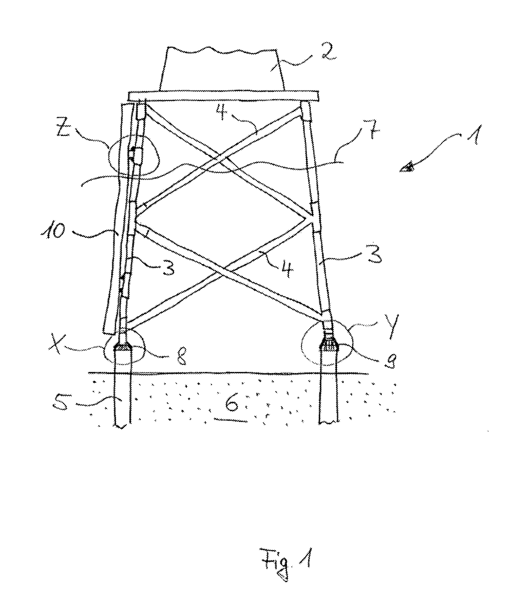
[0037]FIG. 1 shows a foundation structure 1 for a tower structure 2. This foundation structure 1 is a jacket for an offshore structure such as, for example, for an offshore wind turbine, which means that the jacket is anchored to the sea floor 6, wherein the foundation structure 1 is configured and arranged that its upper part is above sea level 7.

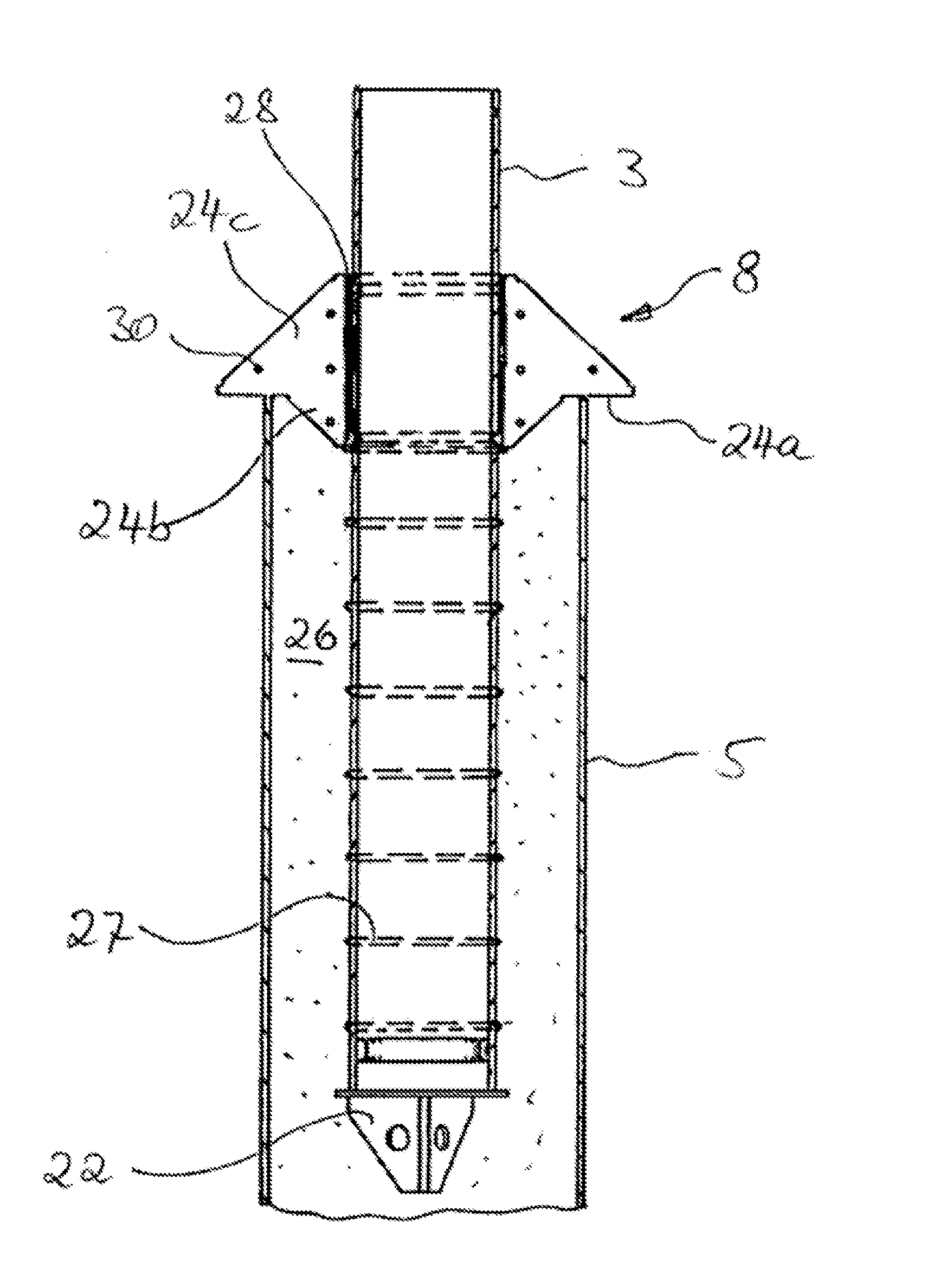
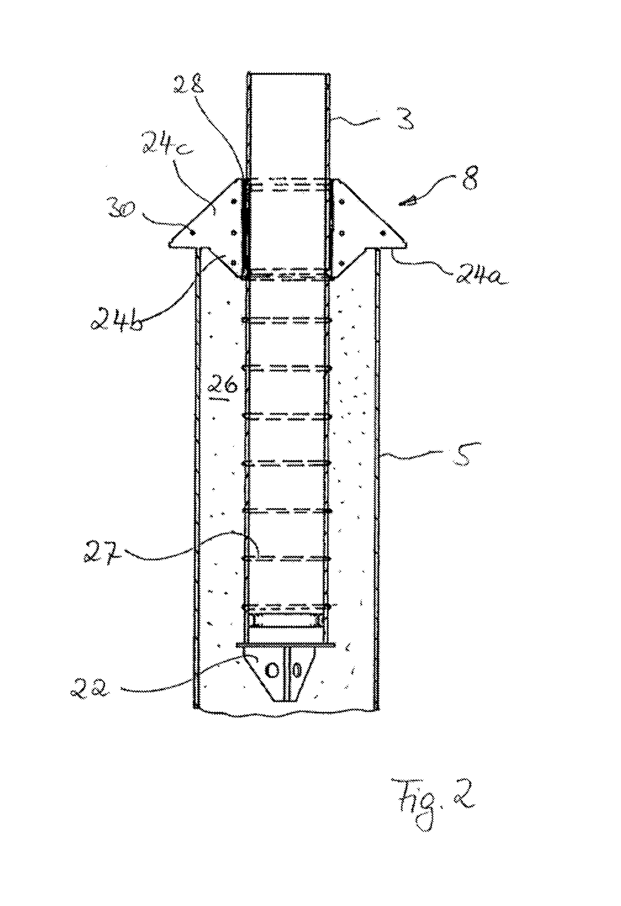
[0038]The jacket consists of corner posts 3 and struts 4 which are arranged between the corner posts 3 and secured thereto. These components are load-dissipating parts, which are referred to as primary structures. The corner posts 3 are anchored via hollow foundation piles 5 in seabed 6, wherein the insertion depth of the corner posts 3 in the foundation piles 5 is limited by pile stoppers 8, 9. As will be shown later in detail, FIG. 1 shows two different pile stoppers, namely pile stopper 8 adhesively secured at the left corner post, pile stopper 9 connected by grout at the right corner post.

[0039]FIG. 2 shows the section designated with ...


PUM


Abstract

An openwork load-bearing structure for a wind turbine, in particular a lattice-tower structure for a wind turbine, in particular a foundation structure for a wind turbine, in particular for anchoring an offshore wind turbine in the ground via driven foundation piles, wherein the openwork load-bearing structure has primary structures, via which loads which occur in the load-bearing structure as a result of the wind turbine are dissipated, and secondary structures, which perform functional, rather than load-dissipating, tasks, wherein the secondary structures are arranged on the primary structures and are connected integrally thereto, and wherein the integral connection between the primary and the secondary structures is in the form of a connecting layer arranged therebetween. Also, a method for producing a lattice-tower structure for a wind turbine, in particular a foundation structure for a wind turbine, in particular for anchoring an offshore wind turbine in the ground via foundation piles.

Description

BACKGROUND OF INVENTION[0001]1. Field of Invention[0002]The present invention relates to an openwork load-bearing structure, in particular a lattice tower structure for a wind turbine. In particular, the invention relates to a foundation structure, which is embodied as an openwork load-bearing structure, in particular as a lattice tower structure, and which is anchored to the ground, for example, as an offshore foundation structure by means of driven foundation piles, in particular by means pre-driven hollow piles. Furthermore, the present invention relates to a method for producing an openwork load-bearing structure, in particular a lattice tower structure.[0003]2. Brief Description of Related Art[0004]Openwork load-bearing structures include, for example, tripods, tripiles or lattice tower structures. The invention will be discussed using such lattice tower structures as an example, without this being intended to be limiting. Lattice tower structures in the context of wind turbine...

Claims


Application Information

Patent Timeline
Patent Type & Authority Applications(United States)
IPC IPC(8): E04B1/41E02D27/42E04H12/22E04B1/19E04H12/34
CPCE02D27/42E02D27/425E04H12/34E04B1/4114E04H12/22E04B1/19
Inventor SEIDEL, MARC
Owner SIEMENS GAMESA RENEWABLE ENERGY SERVICE GMBH
Learn More