
Light fixture with tilting light and fixed heat sink

a technology of tilting light and heat sink, which is applied in the direction of fixed installation, lighting and heating equipment, lighting support devices, etc., can solve the problems of recessed light fixtures, more significant emergencies, and generate heat, and achieve the effect of optimizing system effectiveness and high effectiveness

Active Publication Date: 2015-08-06
USAI LLC
View PDF0 Cites 53 Cited by
  • Summary
  • Abstract
  • Description
  • Claims
  • Application Information

AI Technical Summary

Benefits of technology

The present invention is a heat dissipation system for light fixtures that allows for directional lighting. It uses complementary surfaces on first and second heat sinks, which creates contact pressure when the fixture is in operation mode and allows for movement between the sinks when in adjustment mode. This results in a highly effective heat dissipation system and allows for full range of directional lighting orientations by adjusting the light source's angle.

Problems solved by technology

Recessed lighting is very popular in residential and commercial buildings given its unobtrusive and aesthetically pleasing appearance.
However, recessed light fixtures, specifically those with an LED light source, generate heat when the light source is illuminated.
This heat can become substantial and can cause certain components of the light fixture to fail or can cause even more significant emergencies, such as fires.

Method used


Image

  • Light fixture with tilting light and fixed heat sink
  • Light fixture with tilting light and fixed heat sink
  • Light fixture with tilting light and fixed heat sink

Examples


Embodiment Construction

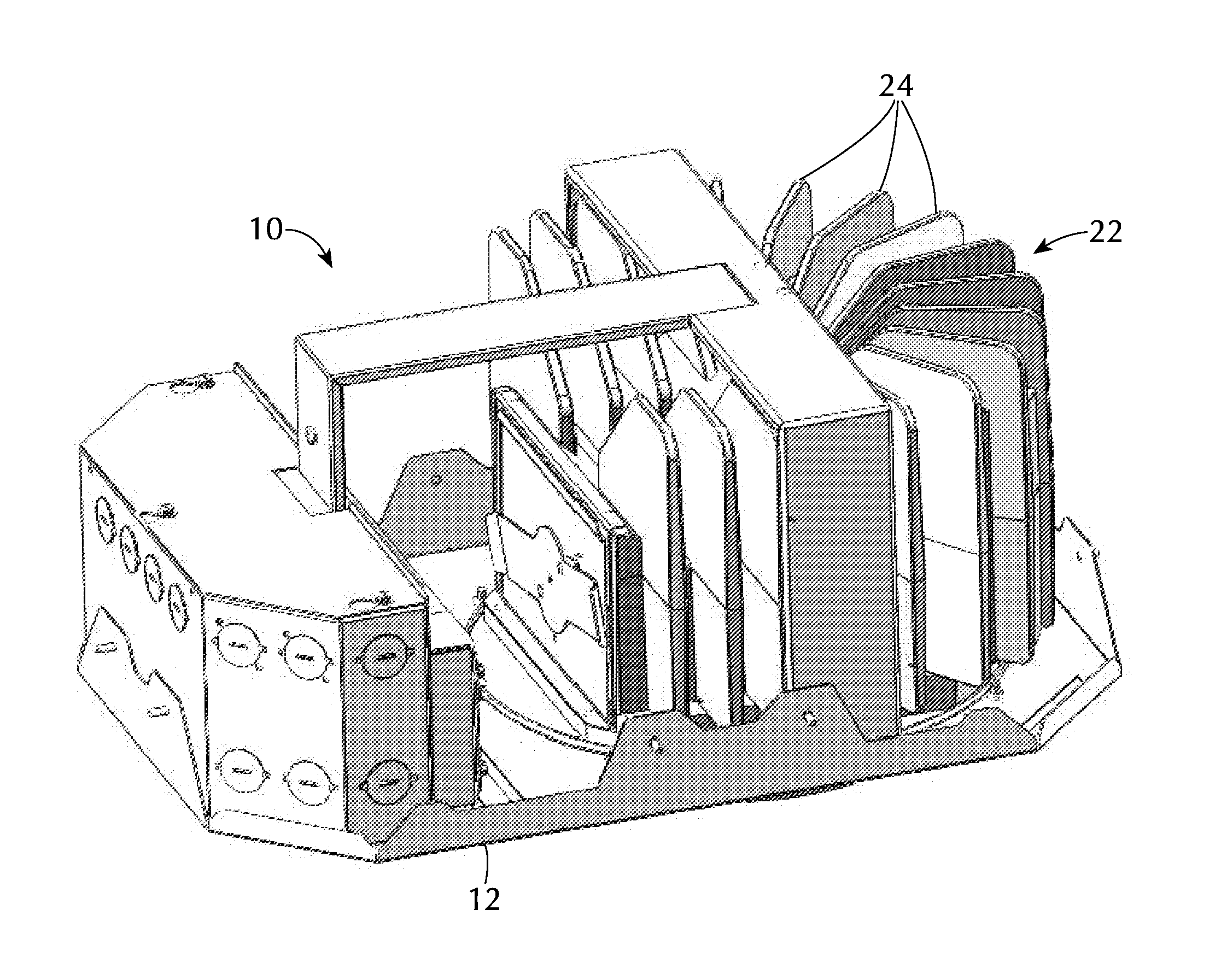
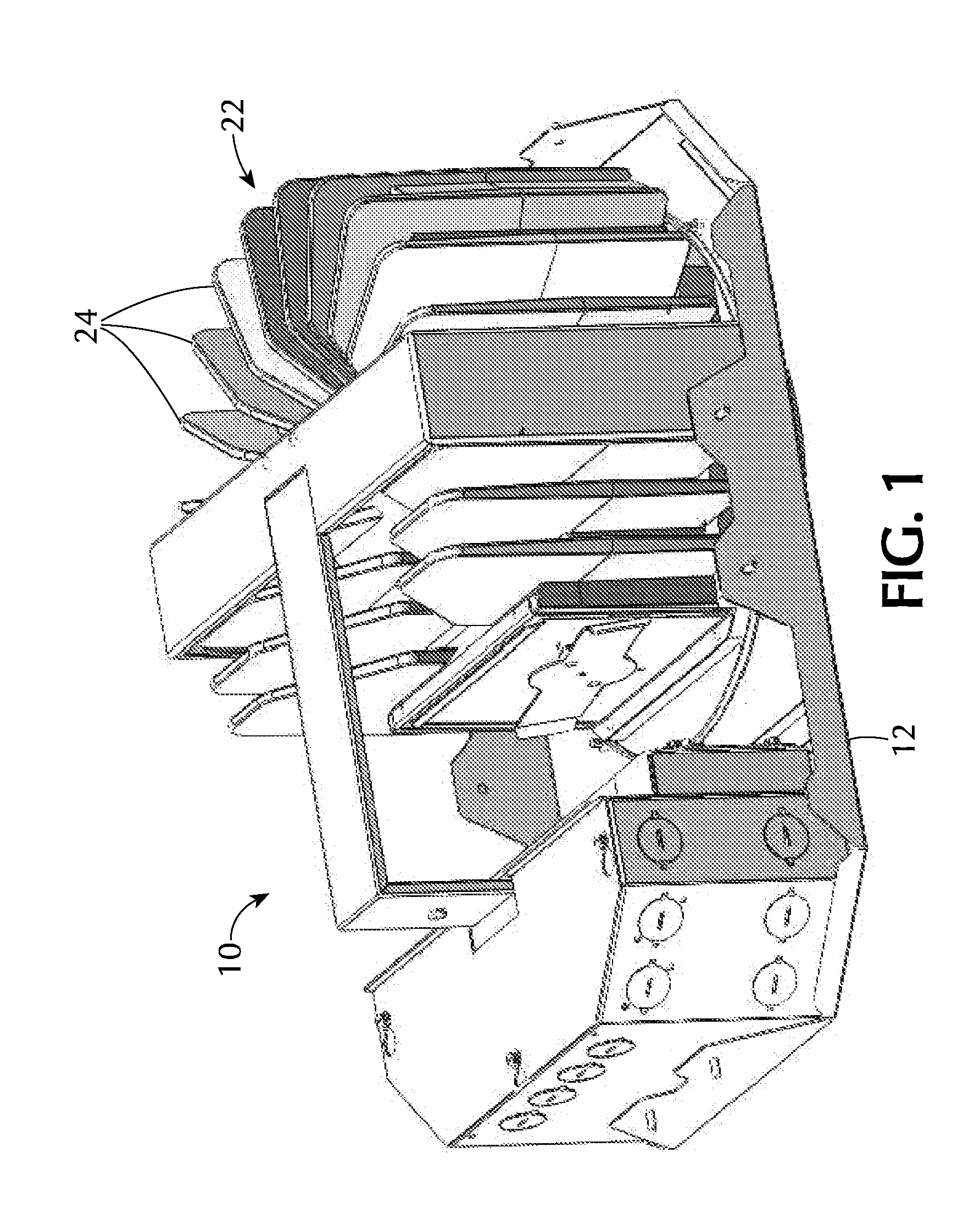
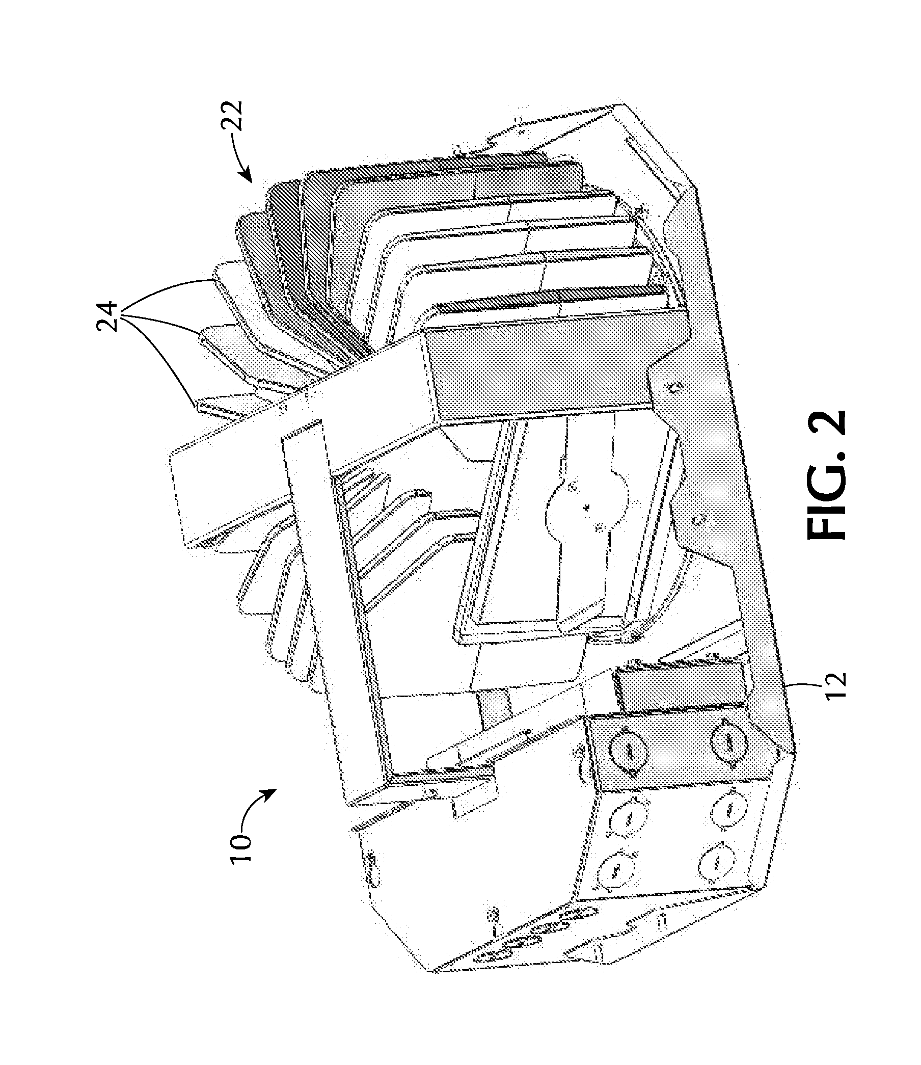
[0032]Referring to FIGS. 1-9, an embodiment of a light fixture 10 constructed in accordance with the invention preferably has a support frame 12 providing a support for affixing the light fixture to an external support structure, such as a ceiling or wall structure (not shown). The light fixture 10 also has a light source 14, such as a Light-Emitting Diode (LED), or another suitable light source, for emitting light through an aperture 30 of the light fixture 10. The light fixture 10 is adapted to permit tilting and rotation of the light source 14 relative to the support 12 to allow aiming of the light beam emitted from the light fixture.

[0033]The light fixture 10 has a heat dissipation system comprising several heat sinks, preferably comprised of thermally conductive material such as aluminum (or another suitable material), which cooperate to dissipate heat generated by the light source, while allowing for adjustment of tilt and rotation positions of the light source. The heat dissi...


PUM


Abstract

A light fixture having a light source, first and second heat sinks with corresponding first and second thermal interfaces having complementary curved surfaces, and a linkage having cams, and springs to create contact pressure between the thermal interfaces when the light fixture is in an operation mode and to permit movement between the thermal interfaces when the light fixture is in an adjustment mode. When the light fixture is in operation mode, the first and second heat sinks work in combination to provide a highly effective heat dissipation system. When the light fixture is in adjustment mode, the separation created permits the light source to move along an adjustment path to change the angular direction of the light emitted and to rotate about a rotational axis, providing a full range of directional lighting orientations.

Description

FIELD OF THE INVENTION[0001]The invention pertains to the field of light fixtures, and, in particular to adjustable light fixtures.BACKGROUND OF THE INVENTION[0002]Recessed lighting is very popular in residential and commercial buildings given its unobtrusive and aesthetically pleasing appearance. Recessed lighting removes from view all electric hardware and wiring, placing everything behind a wall or ceiling. However, recessed light fixtures, specifically those with an LED light source, generate heat when the light source is illuminated. This heat can become substantial and can cause certain components of the light fixture to fail or can cause even more significant emergencies, such as fires.[0003]As such, there is a need in the art for effective heat dissipation systems for light fixtures employing LED light sources. It is further desirable for the light fixture to provide adjustable orientations of the light source to direct the light emanating from the light fixture. Optimally, ...

Claims


Application Information

Patent Timeline
Patent Type & Authority Applications(United States)
IPC IPC(8): F21V17/02F21V19/02F21V29/70
CPCF21V17/02F21Y2101/02F21V19/02F21V29/70F21S8/02F21V21/30F21V21/40F21V29/713F21V29/74F21Y2115/10
Inventor LITTMAN GATOF, BONNIE A.JONES, JONATHAN I.STARR, ORIANA J.
Owner USAI LLC
Learn More