
Method of creating sample page, program, and image forming system

a sample page and image forming technology, applied in the field of creating a sample page, a program and an image forming system, can solve the problems of difficult determination, color change, and large amount of labor, and achieve the effect of easy output and easy outpu

Inactive Publication Date: 2015-08-06
KONICA MINOLTA INC
View PDF10 Cites 12 Cited by
  • Summary
  • Abstract
  • Description
  • Claims
  • Application Information

AI Technical Summary

Benefits of technology

The present invention provides a method for creating a sample page that allows for easy comparison of special colors and provides a means for determining color differences between sheets used for printing. This solution helps to overcome printing-related issues and provides a more organized and efficient printing process.

Problems solved by technology

In variable printing in which mass printing is performed, there is a problem that the color is being changed as a large number of sheets of printing is performed, even if the color adjustment is performed before the mass printing is started.
However, there is a problem that, to use the past output, extraction of a printed portion of the special color from the mass printed sheets is required, and a lot of labor is required to perform determination related to the readjustment and the determination is not so easy.
Although the printing device described in JP 2012-228836 A can compare the color differences, the printing device cannot visually compare an actual image with the past color as to how the actual image is changed from the past color, with respect to the special color that requires strict management.
Further, the printing device described in JP 2012-228836 A cannot confirm an actual output, with respect to the special color that requires strict management.

Method used


Image

  • Method of creating sample page, program, and image forming system
  • Method of creating sample page, program, and image forming system
  • Method of creating sample page, program, and image forming system

Examples


Embodiment Construction

[0071]Hereinafter, embodiments of the present invention will be described with reference to the appended drawings. However, the scope of the invention is not limited to the illustrated examples. Note that the same element is denoted with the same reference sign in description of the drawings, and overlapping description is omitted. Further, dimension ratios of the drawings are exaggerated for the convenience of description, and the ratios may be different from actual ratios.

[0072]

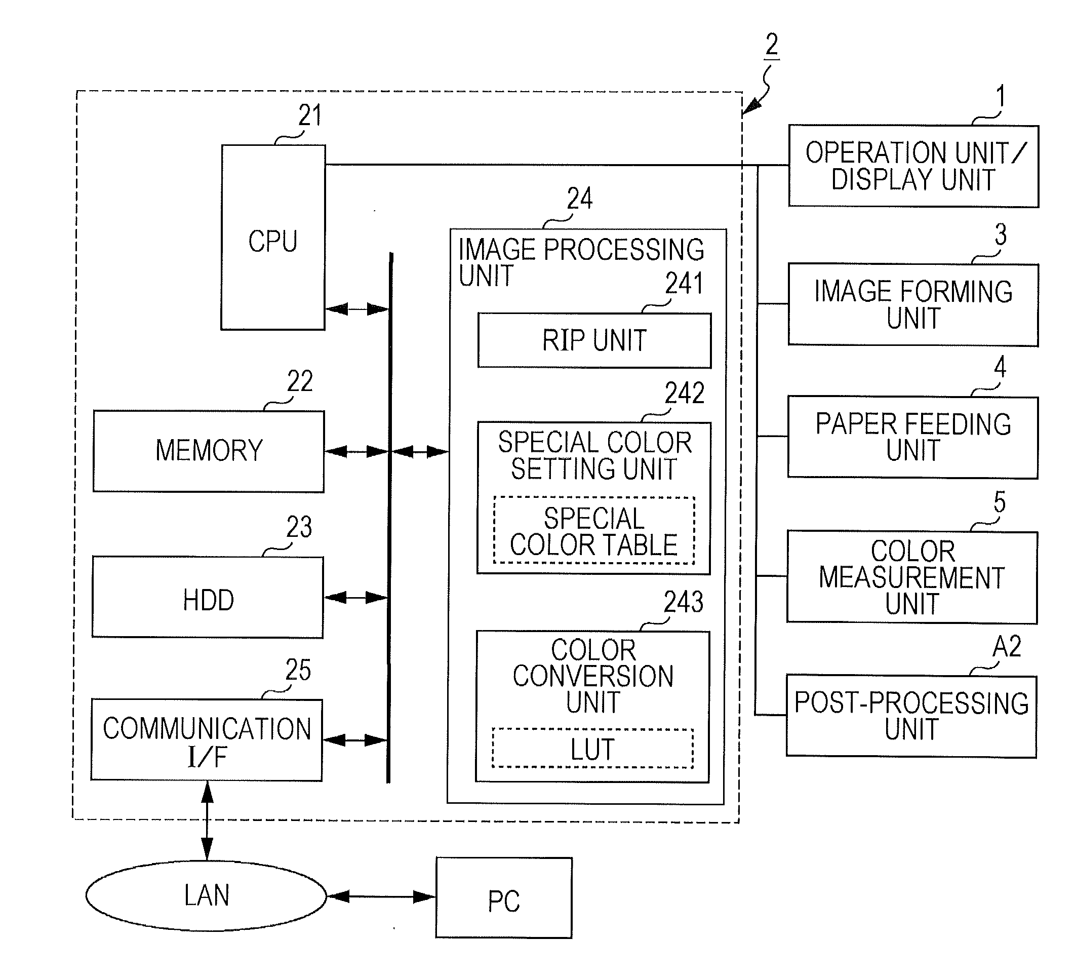
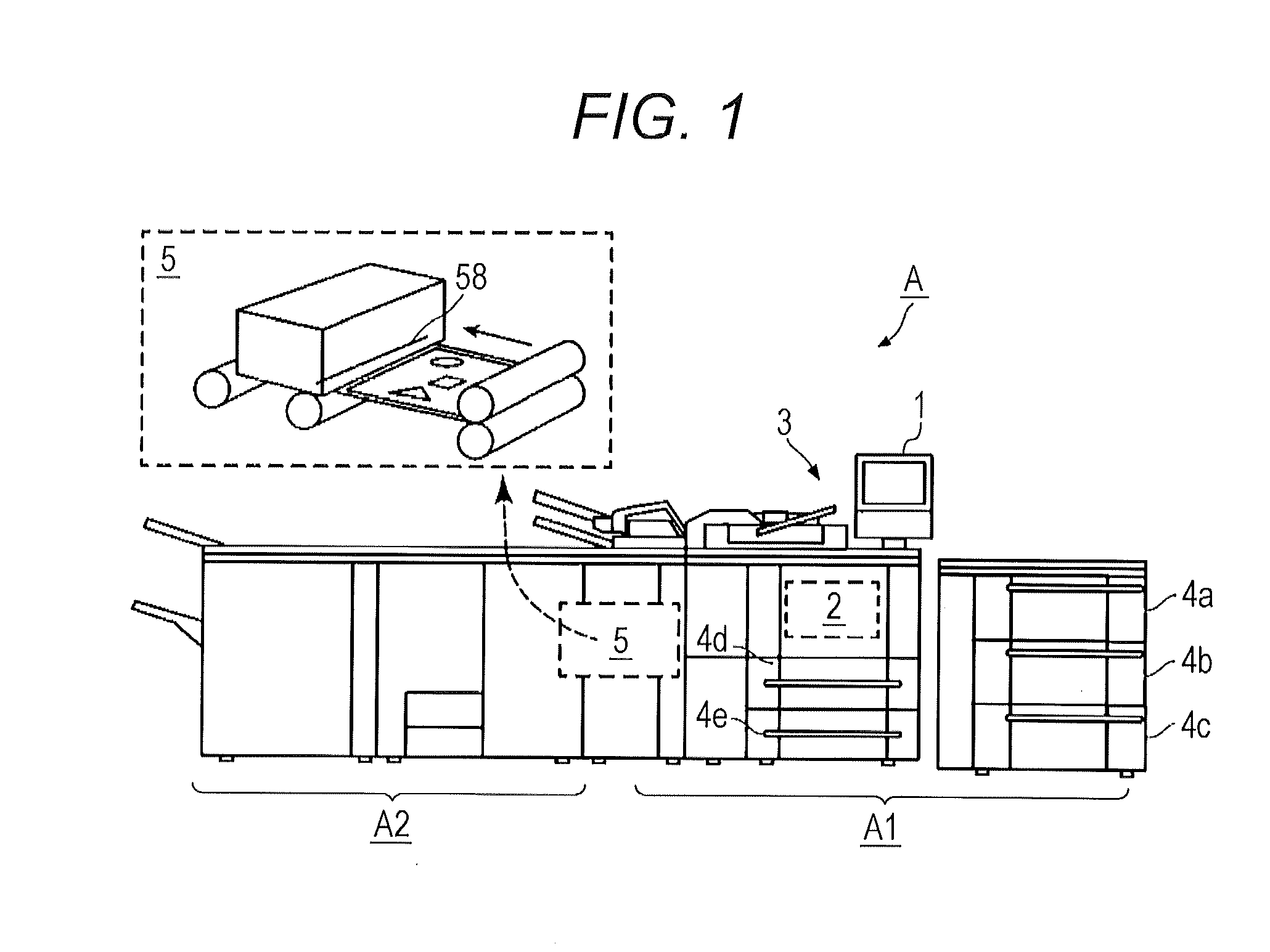
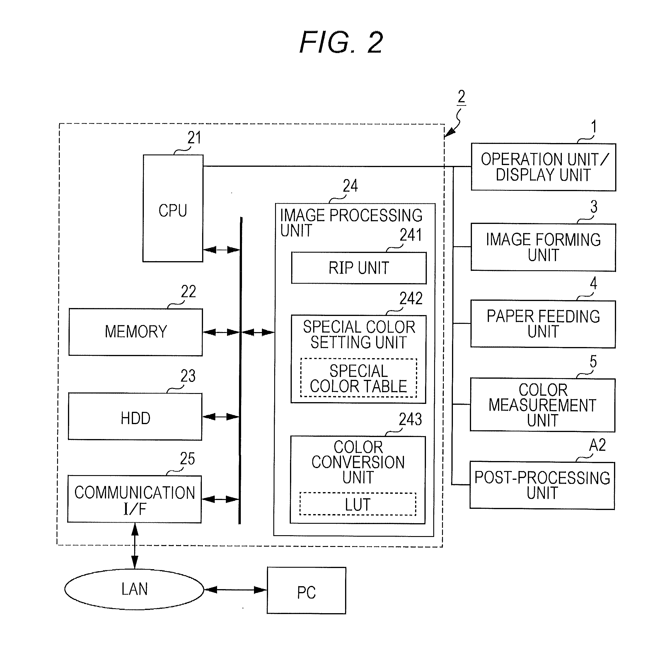
[0073]FIG. 1 is a diagram illustrating an example of a schematic configuration of an image forming system A according Lo an embodiment. FIG. 2 is a block diagram illustrating a hardware configuration example of the image forming system A. FIGS. 3A and 3B are examples of a special color table (“spot color library”) with which identification information of a special color and color information are associated. FIG. 4 is a diagram for describing a look up table (LUT) used for color conversion processing. FIGS. ...


PUM


Abstract

A method of creating a sample page in an image system, the method includes: a step of holding a color measurement result of a colorimeter, with respect to an output image of a special color, as a history color measurement result; a step of determining whether a creation condition of the sample page is satisfied; and a step of creating the sample page having a first color sample image and a second color sample image formed on a recording medium, the first color sample image being according to printer device values calculated based on the history color measurement result of the special color, and the second color sample image being according to printer device values of the special color determined from a special color table, when the creation condition of the sample page is determined to be satisfied.

Description

[0001]The entire disclosures of Japanese Patent Application No. 2014-017944 filed on Jan. 31, 2014 and No. 2014-020760 filed on Feb. 5, 2014 including description, claims, drawings, and abstract are incorporated herein by reference in its entirety.BACKGROUND OF THE INVENTION[0002]1. Field of the Invention[0003]The present invention relates to a method of creating a sample page, a program, and an image forming system.[0004]2. Description of the Related Art[0005]In the printing field, there are colors that require accurate color reproducibility, such as a corporate color used for a logo of a company. Such a color is reproduced by using a specially mixed dedicated ink in offset printing (hereinafter, the color is referred to as “special color (spot color)”).[0006]Meanwhile, in the printing market where image forming devices in an offset printing system are often used, a case of using an image forming device in an electrophotographic system or an image forming device in an ink jet syste...

Claims


Application Information

Patent Timeline
Patent Type & Authority Applications(United States)
IPC IPC(8): G06K15/02G06K15/10G06K15/12
CPCG06K15/027G06K15/102G06K15/129H04N1/6036G03G15/5062B41J29/393G03G15/00H04N1/60
Inventor YAMAMOTO, TOMOKOYAMAMOTO, KAZUTO
Owner KONICA MINOLTA INC
Learn More