
Abridged erase verify method for flash memory

Inactive Publication Date: 2015-08-06
INTEGRATED SILICON SOLUTION
View PDF2 Cites 4 Cited by
  • Summary
  • Abstract
  • Description
  • Claims
  • Application Information

AI Technical Summary

Benefits of technology

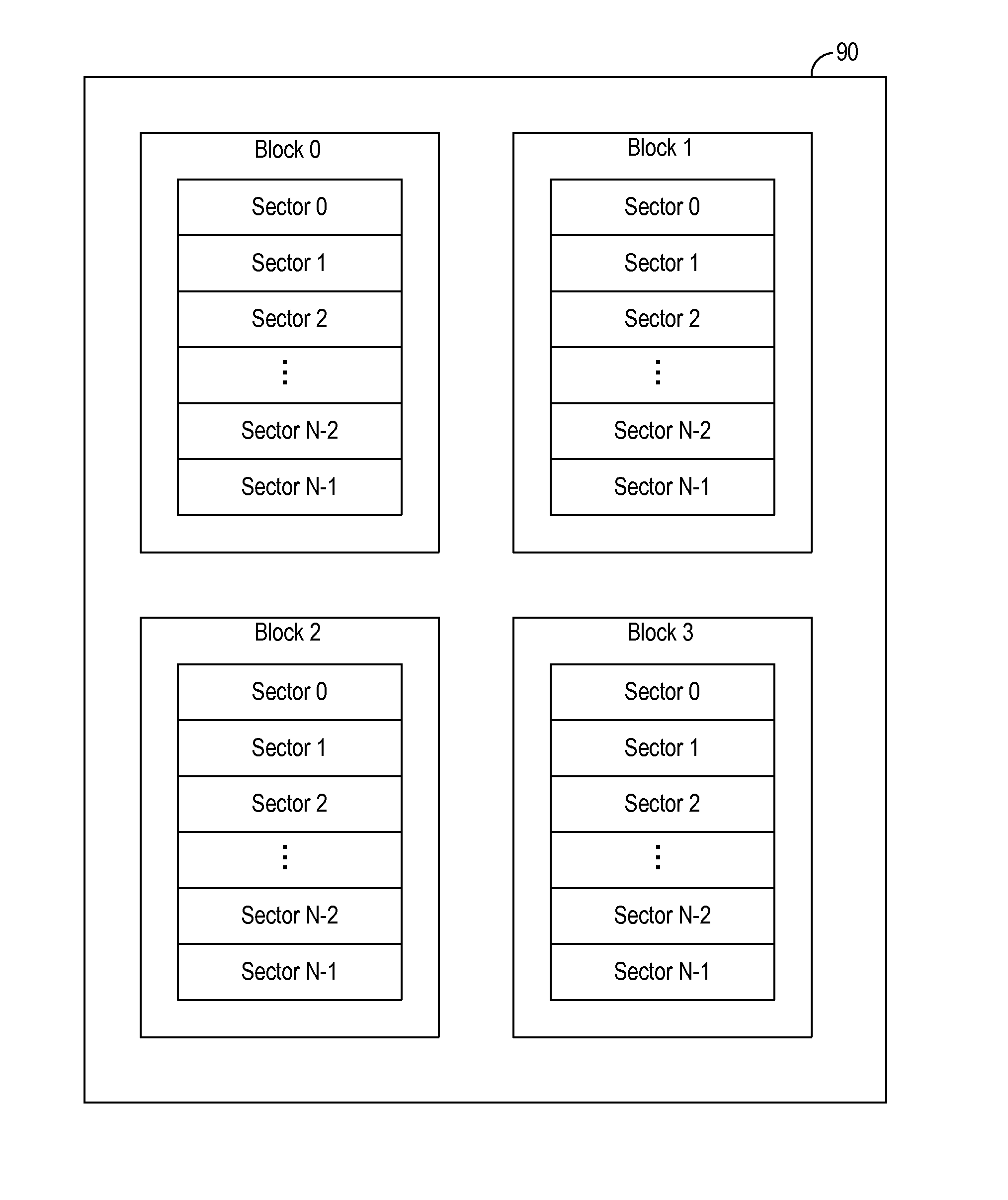
The invention is a method for reducing the time required for erase verify in a flash memory device. The method uses stored failed addresses for each sector in the block during a previous erase verify cycle, instead of starting from the beginning of each sector. This reduces the time required for erase verify and makes the process faster. The invention can be implemented in various ways, such as a process, apparatus, system, or composition of matter. Overall, the invention improves the efficiency and speed of erasing and programming non-volatile memory cells.

Problems solved by technology

Erase and programming operation of non-volatile memory devices require a relatively large voltage and current and erase and programming cycles can be slow.
The erase and verify process can be very long.

Method used


Image

  • Abridged erase verify method for flash memory
  • Abridged erase verify method for flash memory
  • Abridged erase verify method for flash memory

Examples


Embodiment Construction

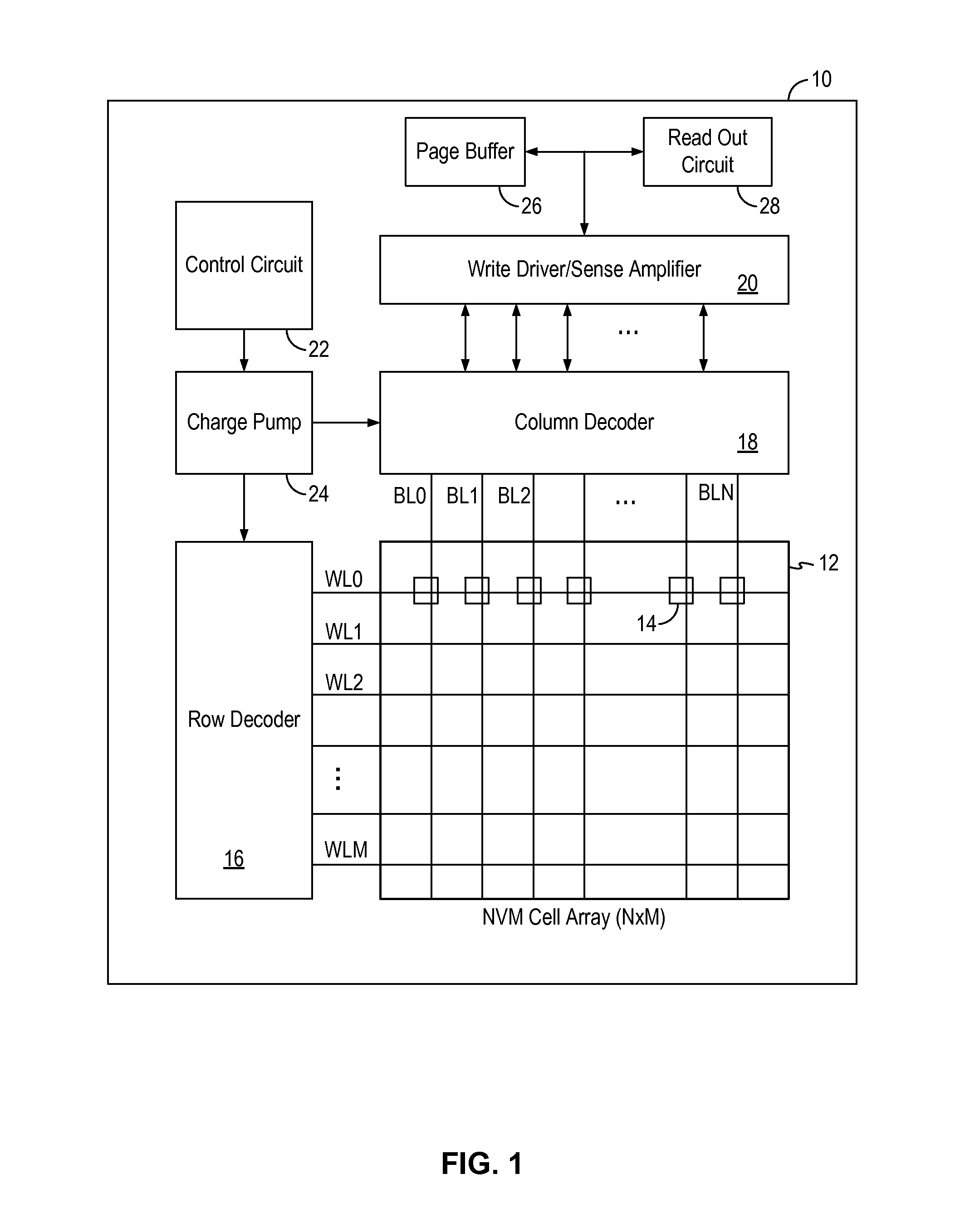
[0012]The invention can be implemented in numerous ways, including as a process; an apparatus; a system; and / or a composition of matter. In this specification, these implementations, or any other form that the invention may take, may be referred to as techniques. In general, the order of the steps of disclosed processes may be altered within the scope of the invention.

[0013]A detailed description of one or more embodiments of the invention is provided below along with accompanying figures that illustrate the principles of the invention. The invention is described in connection with such embodiments, but the invention is not limited to any embodiment. The scope of the invention is limited only by the claims and the invention encompasses numerous alternatives, modifications and equivalents. Numerous specific details are set forth in the following description in order to provide a thorough understanding of the invention. These details are provided for the purpose of example and the inv...


PUM


Abstract

A non-volatile memory device includes a control circuit configured to perform a block erase operation including a block erase cycle and an erase verify cycle on a block of memory cells. The control circuit is configured to perform the erase verify cycle by storing a last verify address for each sector of the block of memory cells, verifying each memory cell in a sector starting from the last verify address for the sector until a memory cell has failed erase verification in that sector, storing the memory cell address of the failed memory cell as the last verify address for that sector, skipping the erase verification for the remaining memory cells in that sector, and continuing the erase verify cycle at a last verify address for the next sector.

Description

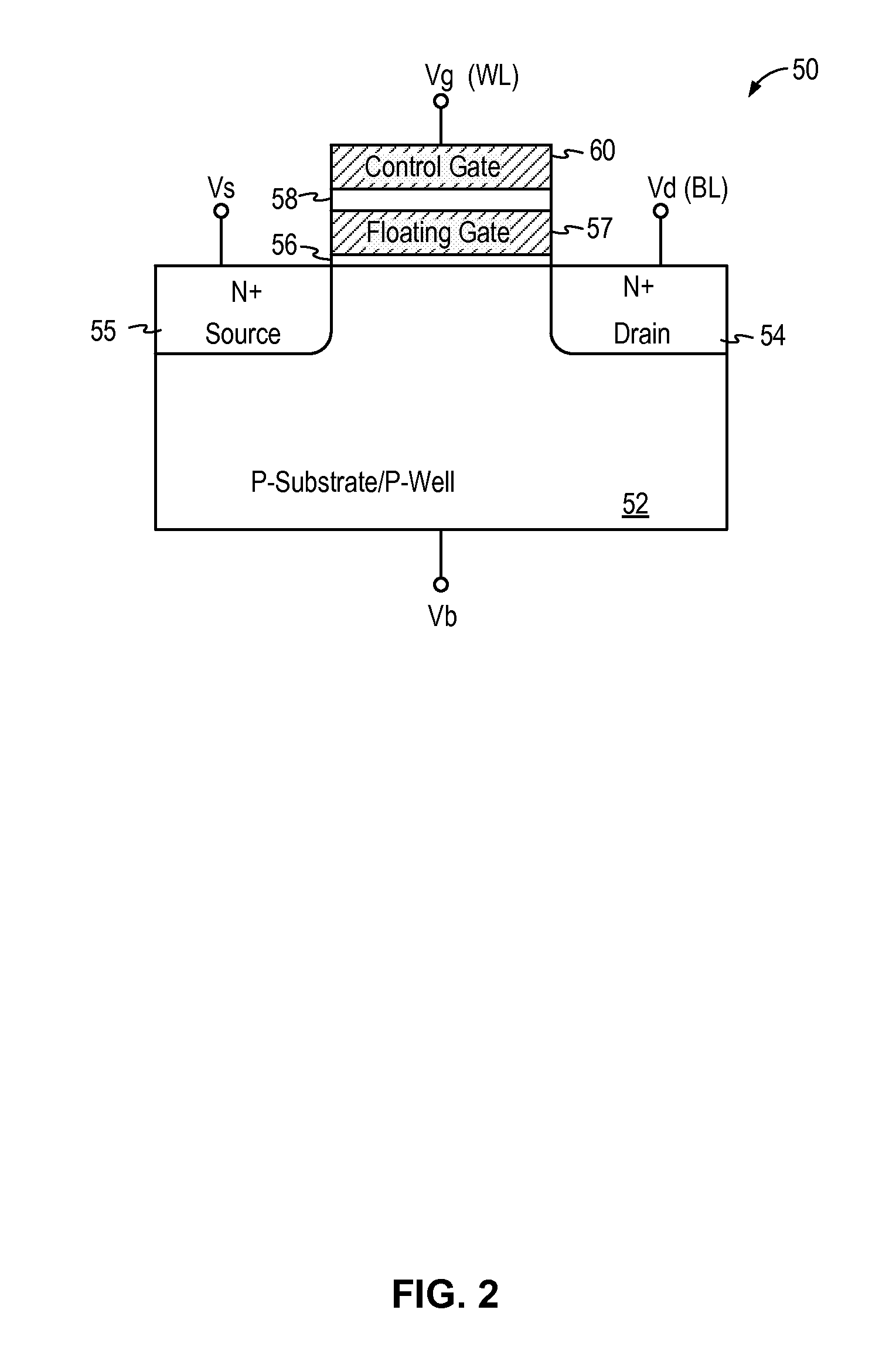
BACKGROUND OF THE INVENTION[0001]Non-volatile memory (NVM) is a memory device that retains content stored therein even when power is removed. EEPROM and flash memory are two commonly used non-volatile memory devices. In particular, flash memory has become widely used in electronic devices, especially portable electronic devices, because of its ability to provide data storage at low power levels. Modern day flash memory devices are typically implemented using a floating gate MOS transistor device as the memory cells. A floating gate MOS transistor device includes a floating gate that is formed between a control gate and the channel region (the substrate) of the MOS device and at least partially vertically aligned with the control gate. Charge storage on the floating gate determines the stored data state (“0” or “1”) of the memory cell.[0002]In a non-volatile memory cell implemented using a floating gate MOS device, programming of the memory cell, or writing data to the memory cell, i...

Claims


Application Information

Patent Timeline
IPC IPC(8): G11C16/34G11C16/08G11C16/16
CPCG11C16/3445G11C16/08G11C16/16
Inventor LEE, JONG SANGJIN, KYOUNG CHON
Owner INTEGRATED SILICON SOLUTION
Learn More