
Electrode assembly including electrode units having the same length and different widths, and battery cell and device including the electrode assembly

a technology of electrode assembly and electrode unit, which is applied in the direction of cell components, flat cell grouping, sustainable manufacturing/processing, etc., can solve the problems of many limitations in battery design, limited shape, and low degree of design freedom of batteries, so as to maintain the capacity and durability characteristics of electrode assemblies, reduce dead space, and improve the degree of design freedom of electrode assemblies

Active Publication Date: 2015-08-06
LG ENERGY SOLUTION LTD
View PDF0 Cites 7 Cited by
  • Summary
  • Abstract
  • Description
  • Claims
  • Application Information

AI Technical Summary

Benefits of technology

The present disclosure allows for the design of an electrode assembly with different widths of electrode units, which results in increased design flexibility and commercial viability of the assembly. The balancing of positive and negative electrodes at interfaces of the different widths results in improved design freedom, reducing dead space and improving spatial efficiency in the device utilizing the electrode assembly.

Problems solved by technology

However, in the related art, electrode assemblies are usually manufactured by stacking unit cells or electrodes having the same size and thus have limited shapes.
Therefore, there are many limitations in terms of battery designs.
However, since such batteries having stepped portions are manufactured by cutting positive electrode plates and negative electrode plates into different sizes to form unit cells having different sizes and stacking the unit cells, the thicknesses of layers of the batteries are limited to multiples of the thicknesses of the unit cells, and thus the degree of design freedom of the batteries is relatively low.
Furthermore, the above-mentioned technique of the related art only discloses a simple idea of changing the design of a battery by cutting positive and negative electrodes into desired sizes and stacking the positive and negative electrodes.
For example, although unit cells of a battery having a stepped portion have no individual operational errors, the unit cells may have overall operation errors, according to the stacked structure of the unit cells, or the electrical capacity of the battery having a stepped portion may be very low as compared with the capacity of a battery having the same volume.
In addition, as charging and discharging cycles are repeated, interfaces between layers of the battery having a stepped portion may swell excessively, lowering the lifespan of the battery and making it difficult to use the battery practically.
However, in the related art, batteries having stepped portions are not designed with the prevention of such problems in mind.

Method used


Image

  • Electrode assembly including electrode units having the same length and different widths, and battery cell and device including the electrode assembly
  • Electrode assembly including electrode units having the same length and different widths, and battery cell and device including the electrode assembly
  • Electrode assembly including electrode units having the same length and different widths, and battery cell and device including the electrode assembly

Examples


example 2

[0156]The positive electrode (A) and the negative electrode (A) were cut into 100 mm×150 mm, and were stacked with a separator being interposed therebetween to form an electrode unit. Then, a relatively small-area electrode unit was formed by cutting the positive electrode (A) and the negative electrode (B) to be 80 mm×150 mm and stacking the positive electrode (A) and the negative electrode (B) with a separator being interposed therebetween. The relatively large-area electrode unit and the relatively small-area electrode unit were stacked to form an electrode assembly.

experimental example 1

[0160]Electric capacities and thickness variations of the electrode assemblies of Examples 1 and 2 and Comparative Examples 1 and 2 were measured after the electrode assemblies undergone 500 charging and discharging cycles.

[0161]The electric capacities were measured under the following charging condition and discharging condition, and charging and discharging were carried out at intervals of 10 minutes.

[0162](1) Charging condition (A): charging to a voltage of 4.2 V or 4.35 V at 1 C rate in constant current mode, and then charging in constant voltage mode until a charging current reaches 1 / 20 of minimum battery capacity

[0163](2) Discharging condition (B): discharging to a voltage of 3 V at 1 C rate in constant current mode

[0164]The thickness variations of the electrode assemblies measured by measuring the thicknesses of the electrode assemblies each time after one charging and discharging cycle.

[0165]Measurement results are shown in FIG. 12. Referring to FIG. 12, in the case of the ...

experimental example 2

[0166]The positive electrode (A) and the negative electrode (E) were cut into 80 mm×150 mm, and were stacked with a separator being interposed therebetween to form a small-area electrode unit.

[0167]Then, negative electrodes 1 to 8 were manufactured in the same manner as in Manufacturing Example 3, except that the thicknesses of the negative electrodes 1 to 8 were varied, as shown in Table 2. The negative electrodes 1 to 8 had reversible capacities as shown in Table 2. Thereafter, the positive electrode (A) and the negative electrodes 1 to 8 were cut into 100 mm×150 mm, and were stacked with separators being disposed therebetween, so as to form large-area electrode units 1 to 8

[0168]Then, small-area electrode units were placed on the large-area electrode units 1 to 8, respectively, so as to form electrode assemblies 1 to 8.

TABLE 2Small-N / Parea PreversibleN / Pthick-ReversiblecapacitythicknessLarge-nessesPorositycapacityratios atratios atNo.area N(μm)(%)(mAh)interfacesinterfacesEA 1N 14...


PUM


Abstract

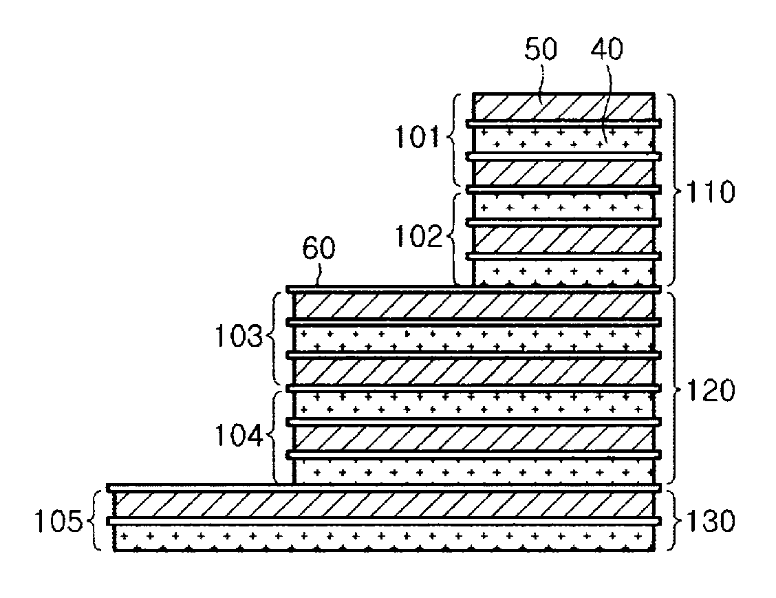
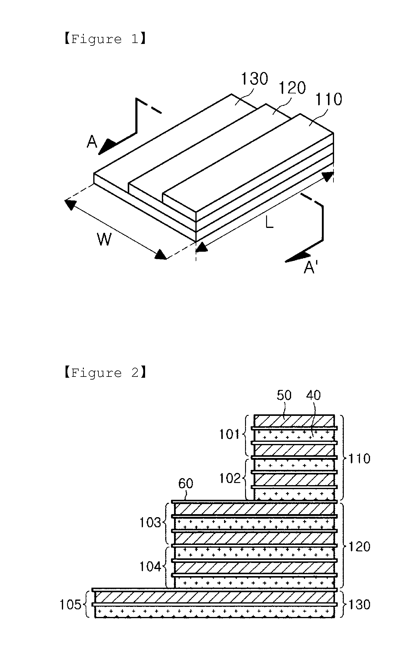
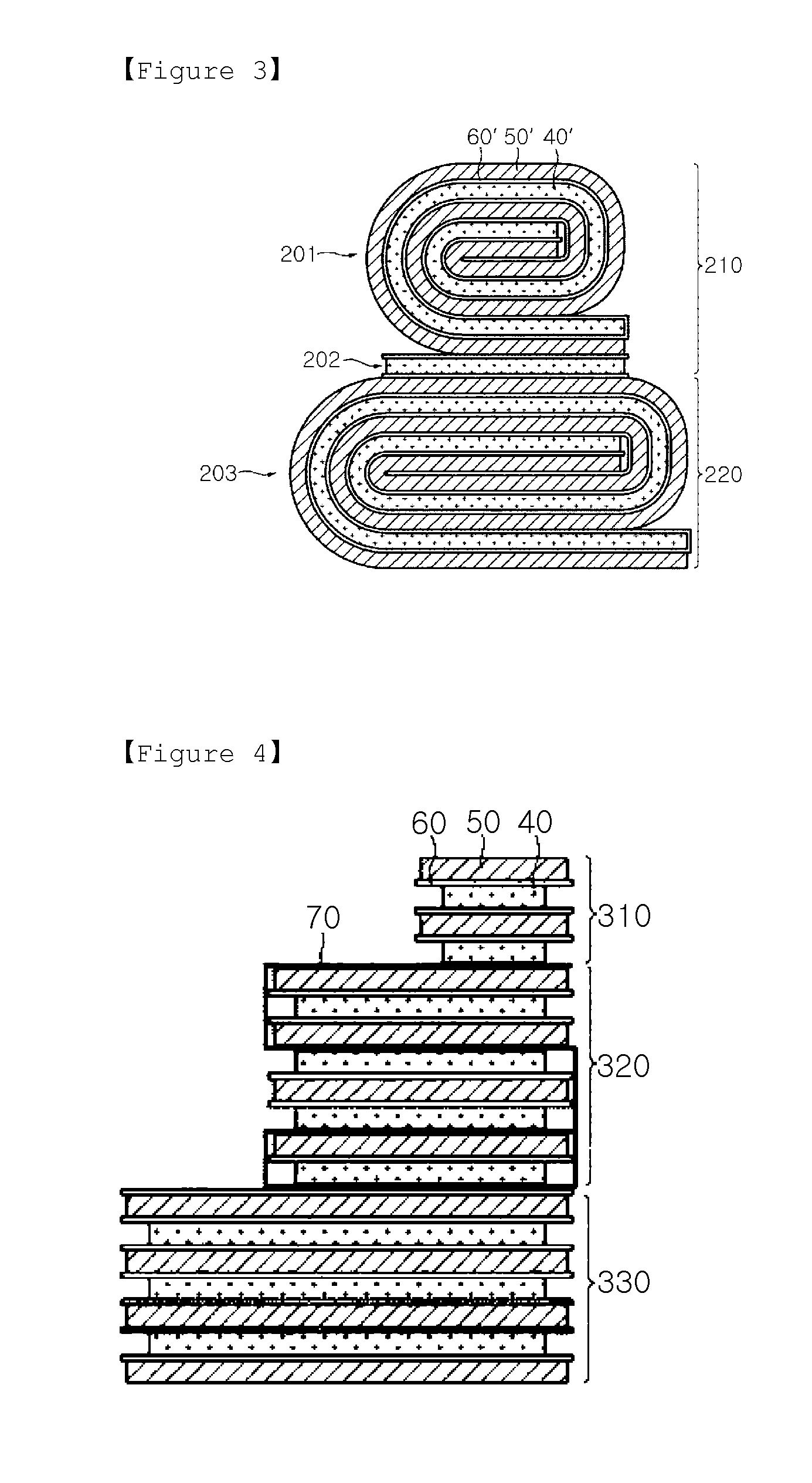
There are provided an electrode assembly, a battery cell including the electrode assembly, and a device including the electrode assembly. The electrode assembly includes a combination of two or more electrode units having the same length and different widths, wherein the electrode units are stacked so that a stepped portion is formed between the electrode units, and electrodes having different polarities face each other at an interface between the electrode units.

Description

TECHNICAL FIELD [0001]The present disclosure relates to an electrode assembly having a stepped portion, and more particularly, to an electrode assembly including electrode units having the same length and different widths, the electrode units being configured such that electrodes having different polarities face each other at interfaces between the electrode units, and a battery including the electrode assembly.[0002]In addition, the present disclosure relates to a battery cell, a battery pack, and a device that include the electrode assembly.BACKGROUND ART[0003]Demand for secondary batteries has markedly increased with the development and increasing usage of mobile devices, and particularly, secondary batteries having high energy density, high operating voltages, easy-to-store characteristics, and relatively long lifespans are widely used as power sources in various electronic products such as mobile devices.[0004]Generally, secondary batteries such as lithium secondary batteries a...

Claims


Application Information

Patent Timeline
IPC IPC(8): H01M10/0585H01M10/0525H01M10/0587
CPCY02E60/122H01M10/052H01M10/0525H01M10/0587Y02T10/7011H01M10/0585Y02E60/10Y02P70/50H01M10/0583Y02T10/70
Inventor KWON, SUNG-JINKIM, KI-WOONGAHN, SOON-HOKIM, DONG-MYUNGKIM, YOUNG-HOONYOON, SUNG-HANRYU, SEUNG-MIN
Owner LG ENERGY SOLUTION LTD
Learn More