
Liquid Ejecting Apparatus

a liquid ejecting apparatus and liquid technology, applied in printing and other directions, can solve the problems of liquid ejection failure, deterioration of deaeration efficiency, and decreased ink deaeration in the liquid storage chamber

Active Publication Date: 2015-08-13
SEIKO EPSON CORP
View PDF3 Cites 21 Cited by
  • Summary
  • Abstract
  • Description
  • Claims
  • Application Information

AI Technical Summary

Benefits of technology

This invention provides a liquid ejecting apparatus with reduced mixing of air bubbles into liquid during ejection. The apparatus includes a deaeration unit and a flexible unit that regulates the pressure of the liquid in the system. The invention also includes a foreign substance capturing unit to prevent foreign substances from contaminating the system. Additionally, the invention allows for efficient deaeration and the circulation of liquid through the system without interfering with the ejection process.

Problems solved by technology

However, since a degree of deaeration of ink in the liquid storage chamber is decreased when ink containing air bubbles is collected, there is a problem in that deaeration of ink should be performed every time circulation is performed, and efficiency of deaeration deteriorates.
In addition, such a problem is not limited to a printer which performs printing by ejecting pigment ink, and is generally common to liquid ejecting apparatuses in which there is a concern that air bubbles which grow in liquid or air bubbles which are mixed into liquid may cause an ejection failure of liquid.

Method used


Image

  • Liquid Ejecting Apparatus
  • Liquid Ejecting Apparatus
  • Liquid Ejecting Apparatus

Examples


Embodiment Construction

[0028]Hereinafter, embodiments of a liquid ejecting apparatus will be described with reference to drawings. The liquid ejecting apparatus is, for example, an ink jet printer which performs recording (printing) by ejecting pigment ink which is an example of liquid on a medium such as a sheet.

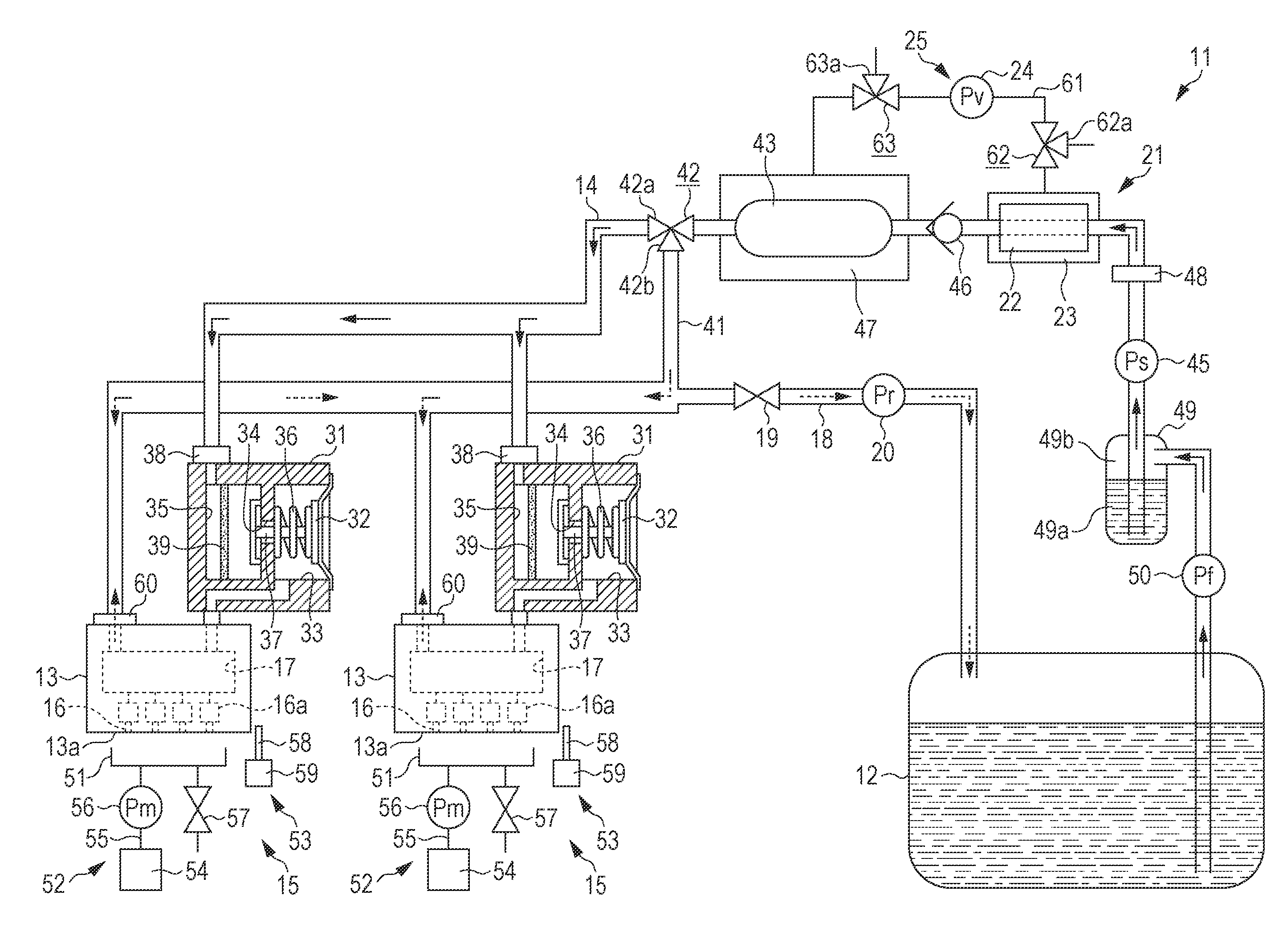
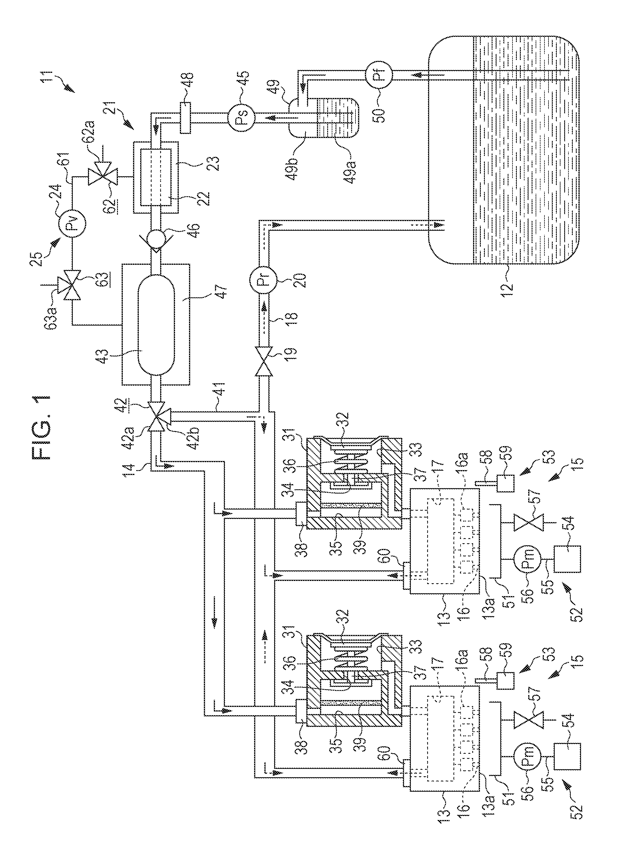
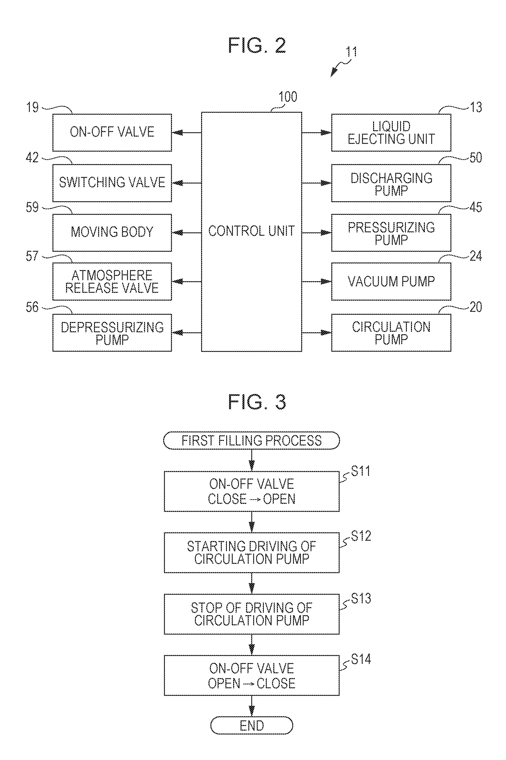
[0029]As illustrated in FIG. 1, a liquid ejecting apparatus 11 includes a liquid accommodation unit 12 which accommodates liquid, a plurality of liquid ejecting units 13 which eject liquid, a liquid flow path 14 for supplying liquid which is accommodated in the liquid accommodation unit 12 to the liquid ejecting unit 13, and a maintenance unit 15 which performs maintenance of the liquid ejecting unit 13. The liquid accommodation unit 12 is also be configured so as to pour liquid through a pouring hole (not illustrated) in a state of being mounted on the liquid ejecting apparatus 11, and it is also possible to adopt a configuration in which a carriage-shaped liquid accommodation unit 12 is detacha...


PUM


Abstract

A liquid ejecting apparatus includes a plurality of nozzles which eject liquid; a common liquid chamber which supplies liquid to the plurality of nozzles; a liquid flow path for supplying liquid which is accommodated in a liquid accommodation unit to the common liquid chamber; a deaeration unit which deaerates liquid in the liquid flow path; a liquid flow unit which causes liquid in the liquid flow path to flow; a return flow path which connects the common liquid chamber and the liquid accommodation unit; and an on-off valve which closes the return flow path by being in a closed state.

Description

CROSS REFERENCE TO RELATED APPLICATION(s)[0001]This application claims priority under 35 U.S.C. §119 to Japanese Application No. 2014-022005, filed Feb. 7, 2014, the content of which is hereby incorporated by reference in its entirety.BACKGROUND[0002]1. Technical Field[0003]The present invention relates to a liquid ejecting apparatus such as a printer.[0004]2. Related Art[0005]As an example of a liquid ejecting apparatus, there is an ink jet printer which performs printing by ejecting ink from nozzles which are provided in a recording head. Among such printers, there is a printer which suppresses dot omission which occurs when air bubbles are mixed in nozzles by performing deaeration of ink in a liquid storage chamber which stores ink which will be supplied to a recording head (for example, JP-A-2013-75371).[0006]Meanwhile, in the above described printer, sedimentation of a pigment component which is included in ink is suppressed by circulating ink between a liquid storage chamber a...

Claims


Application Information

Patent Timeline
Patent Type & Authority Applications(United States)
IPC IPC(8): B41J2/19B41J2/175
CPCB41J2/17596B41J2/19B41J2/175B41J2/18
Inventor OTSUKA, NOBUTOSHISHIMAZAKI, JUN
Owner SEIKO EPSON CORP
Learn More