
Seismic isolation structure for equipment, and seismic isolation method

Active Publication Date: 2015-08-13
ANSHIN
View PDF12 Cites 11 Cited by
  • Summary
  • Abstract
  • Description
  • Claims
  • Application Information

AI Technical Summary

Benefits of technology

The present invention offers seismic isolation structures and methods that use a gel-like elastic body and a plastically deformable support body to absorb vibration and prevent damage to equipment. This eliminates the need for anchor bolts, making it suitable for a variety of floor surfaces and equipment. The structures also improve vibration-proof, sound-proof, and seismic performance of existing equipment while providing a hygienic seismic isolation structure through simple installation work.

Problems solved by technology

Conventional seismic isolation structures using anchor bolts, however, are not only inapplicable to waterproof floor surfaces or transportable equipment but also require large-scale earthquake-proof works for existing equipment.
According to the conventional seismic isolation structures using vibration-proof rubber, disadvantageously, a lateral vibration of earthquakes tends to cause the leg sections of heavy objects to slide laterally, and the earthquake-proof works may render the installation environment of the equipment unhygienic as rubbish and impurities tend to gather around the vibration-proof rubber.

Method used


Image

  • Seismic isolation structure for equipment, and seismic isolation method
  • Seismic isolation structure for equipment, and seismic isolation method
  • Seismic isolation structure for equipment, and seismic isolation method

Examples


embodiment 1

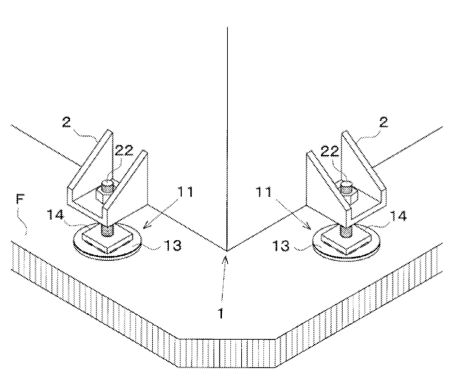
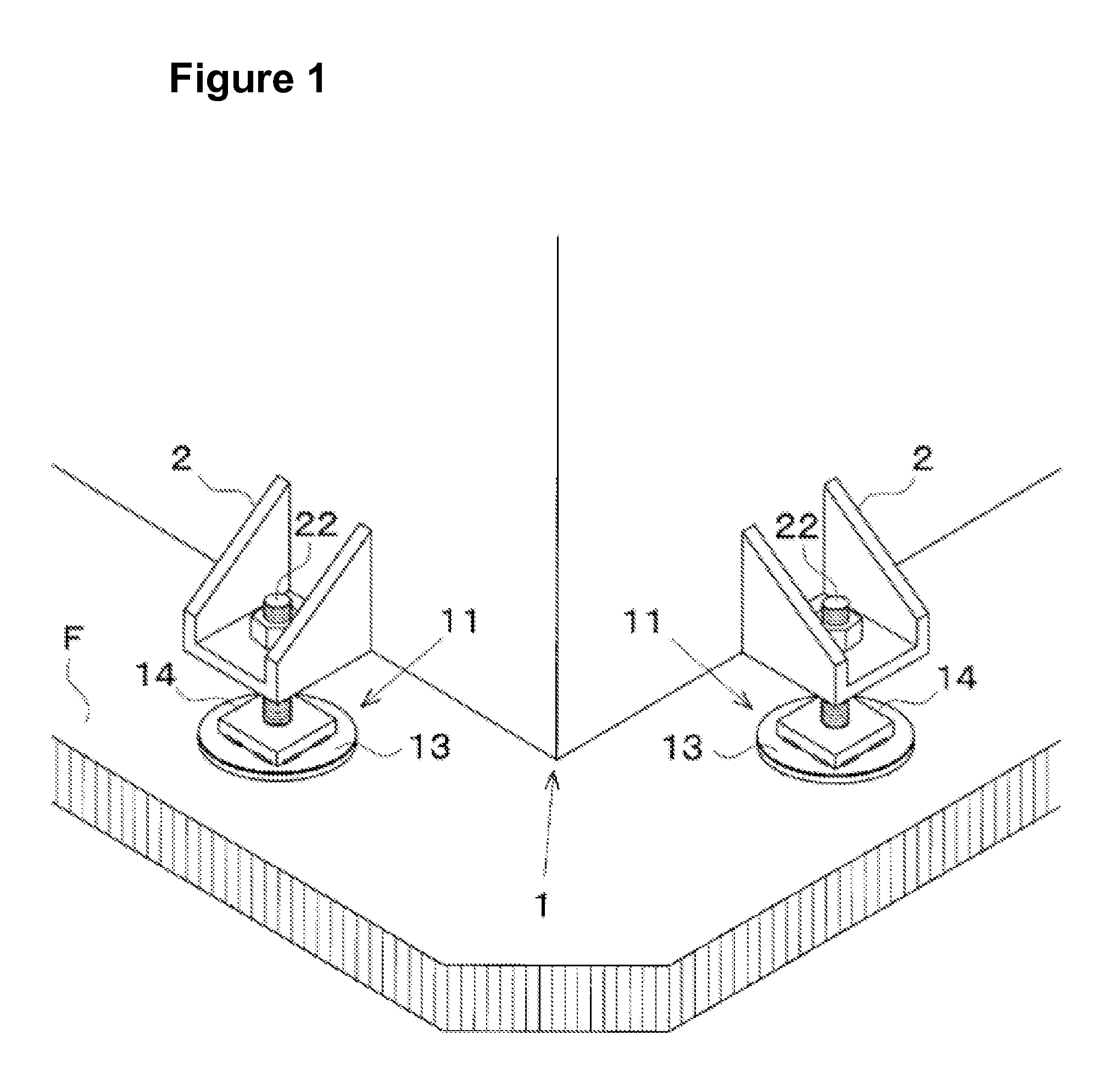
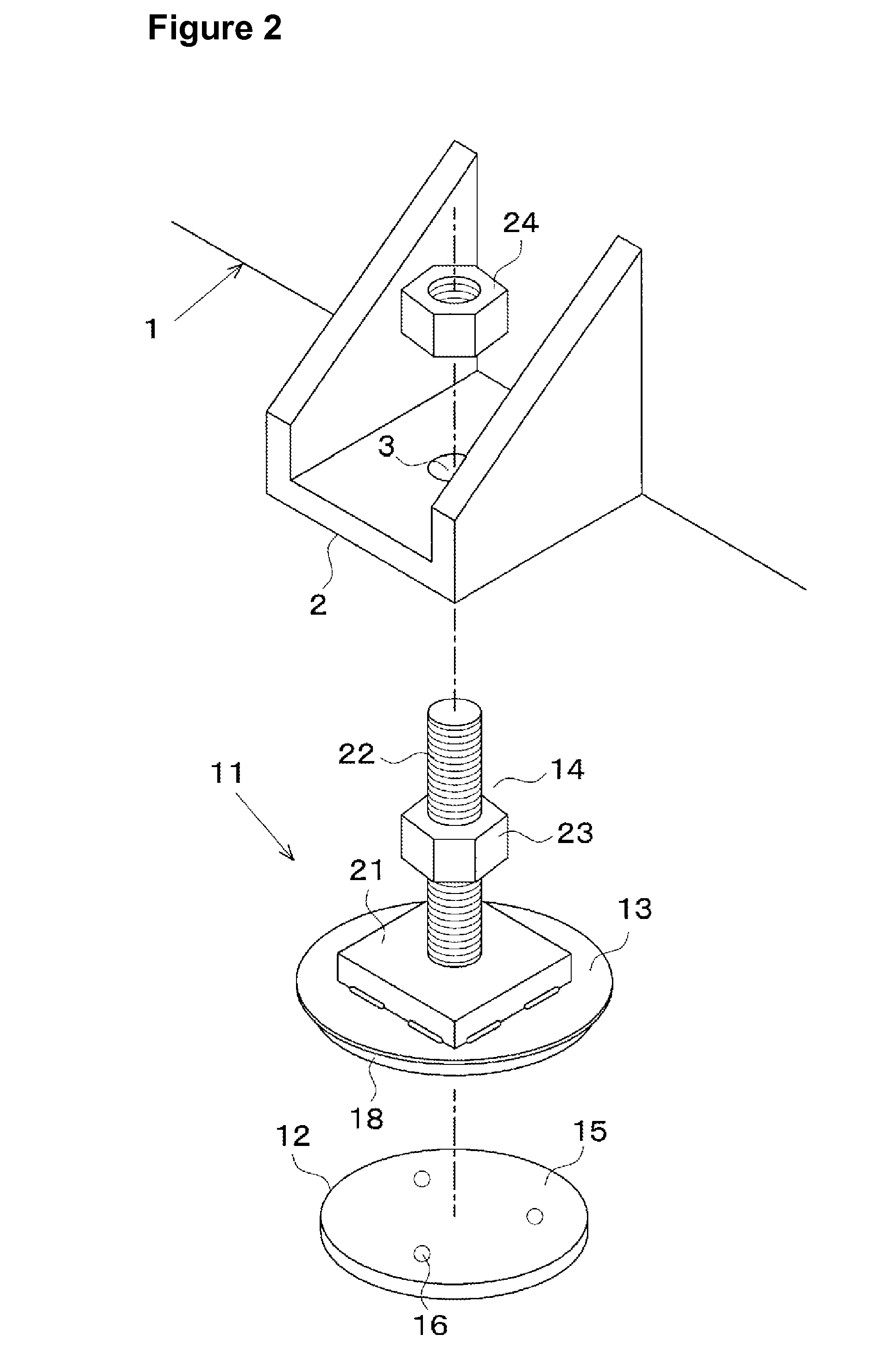
[0038]As shown in FIGS. 1 and 2, the seismic isolation structures 11 of Embodiment 1 are provided between a piece of equipment 1, which is a heavy object, and a waterproofed floor surface F. The equipment 1 includes a plurality of leg portions 2, whereas the seismic isolation structures 11 include mechanisms for adjusting the heights of the leg portions 2 with respect to the floor surface F. The seismic isolation structures 11 are provided with vibration-damping pads 12 (see FIG. 2) set on the floor surface F, pressurizing plates 13 that press against the vibration-damping pads 12, and holders 14 that restrain the leg portions 2 of the equipment 1 on the pressurizing plates 13.

[0039]As shown in FIGS. 2 and 3, a vibration-damping pad 12 is comprised of a gel-like elastic body 15 having elasto-viscosity and plastically deformable support bodies 16. The gel-like elastic body 15 is formed of a transparent or translucent polymeric material in a circular shape. Adhesive layers 15a and 15b...

embodiment 2

[0046]In the seismic isolation structure 211 shown in FIGS. 6 and 7, the base 21 of the holder 14 is clamped to the pressurizing plate 13 by four arcuate members 28 with a vibration-proof rubber 29 interposed between the base 21 and the pressurizing plate 13. The arcuate members 28 are assembled to intersect one another and fastened to bolts 31 provided on the pressurizing plate 13 with nuts 30. Bonded to the under surface of the base 21 is an intermediate plate 32 that is provided with a restraint wall 34 formed along the circumference thereof for blocking a caulking compound 33. Additionally, the vibration-proof rubber 29 is disposed within the restraint wall 34 via a gap 35 such that the two upper and lower tiers of elastic members comprised of the vibration-proof rubber 29 and the vibration-damping pad 12 are configured to provide improved vibration absorption. Moreover, the two upper and lower tiers of caulking compounds 20 and 33 are configured to ensure a hygienic environment...

embodiment 3

[0047]According to the seismic isolation structure 311 shown in FIGS. 8 and 9, the holder 14 includes a columnar member 36 surrounding a leg section 6 of equipment 5 (only a part thereof is shown), and the leg section 6 is restrained on the pressurizing plate 13 by the columnar member 36 from moving laterally. The leg section 6 is attached to the equipment 5 in such a manner as to allow adjustment of its height with a screw 7, and the leg section 6 is also removably inserted in the interior of the columnar member 36. As in Embodiment 1, a caulking compound 20 is provided around the vibration-damping pad 12 via the gap 19 and the restraint wall 18. Accordingly, the seismic isolation structure 311 of Embodiment 3 is preferably applicable to equipment, such as kitchen equipment and showcases, that is relatively light in weight and capable of being easily maintained in hygienic condition and need to be transportable. Note that in the illustrated vibration-damping pad 12, a single suppor...


PUM


Abstract

Plastically deformable support bodies (16) are embedded in a gel-like elastic body (15). A bottom-surface adhesive layer (15b) of the gel-like elastic body (15) is bonded to a floor surface (F), and a pressurizing plate (13) is kept on a top-surface adhesive layer (15a). A leg section (2) of equipment (1) is restrained from moving laterally with a bolt (22) provided on the pressurizing plate (13). A load of the equipment (1) is used to apply pressure to a vibration-damping pad (12) via the pressurizing plate (13). A restraint wall (18) is disposed around the vibration-damping pad (12) and a caulking compound (20) is packed in the opening between the pressurizing plate (13) and the floor surface (F). The caulking compound (20) is blocked by the restraint wall (18), and the gel-like elastic body (15) is allowed to deform due to a gap (19) formed between the restraint wall (18) and the vibration-damping pad (12). According to the present invention, a simple and hygienic seismic isolation structure can be used to prevent vibration, noise, and toppling of equipment installed on a floor surface without using anchor bolts.

Description

FIELD OF THE INVENTION[0001]The present invention relates to seismic isolation structures and seismic isolation methods for preventing vibration, noise, and toppling, due to an earthquake, of a variety of equipment, such as machines, tanks, showcases, etc., installed on floor surfaces.TECHNICAL BACKGROUND[0002]Conventionally, facilities installed in factories, etc., are typically secured to the floor surfaces with anchor bolts. For example, the equipment 51 shown in FIG. 13 is installed via nuts 54 on a concrete floor surface F with anchor bolts 53 that penetrate leg portions 52. However, there are types of equipment for which anchor bolts 53 cannot be used as means for preventing its toppling. For example, pieces of equipment on production lines of drinking water or food or in kitchens are installed with their legs set on waterproof floor surfaces F without using anchor bolts in order to meet the hygienic requirements and ensure the transportability of the equipment.[0003]Additiona...

Claims


Application Information

Patent Timeline
IPC IPC(8): E04H9/02
CPCE04H9/028F16F15/02F16M7/00
Inventor SUGITA, KIKUOMURASE, SHINJI
Owner ANSHIN
Learn More