
Hearing aid device comprising a sensor member

a technology of sensor and hearing aid, which is applied in the direction of hearing aid housing, electrical transducer, instruments, etc., can solve the problems of difficult access to parameters and quantification

Active Publication Date: 2015-08-13
OTICON
View PDF3 Cites 93 Cited by
  • Summary
  • Abstract
  • Description
  • Claims
  • Application Information

AI Technical Summary

Benefits of technology

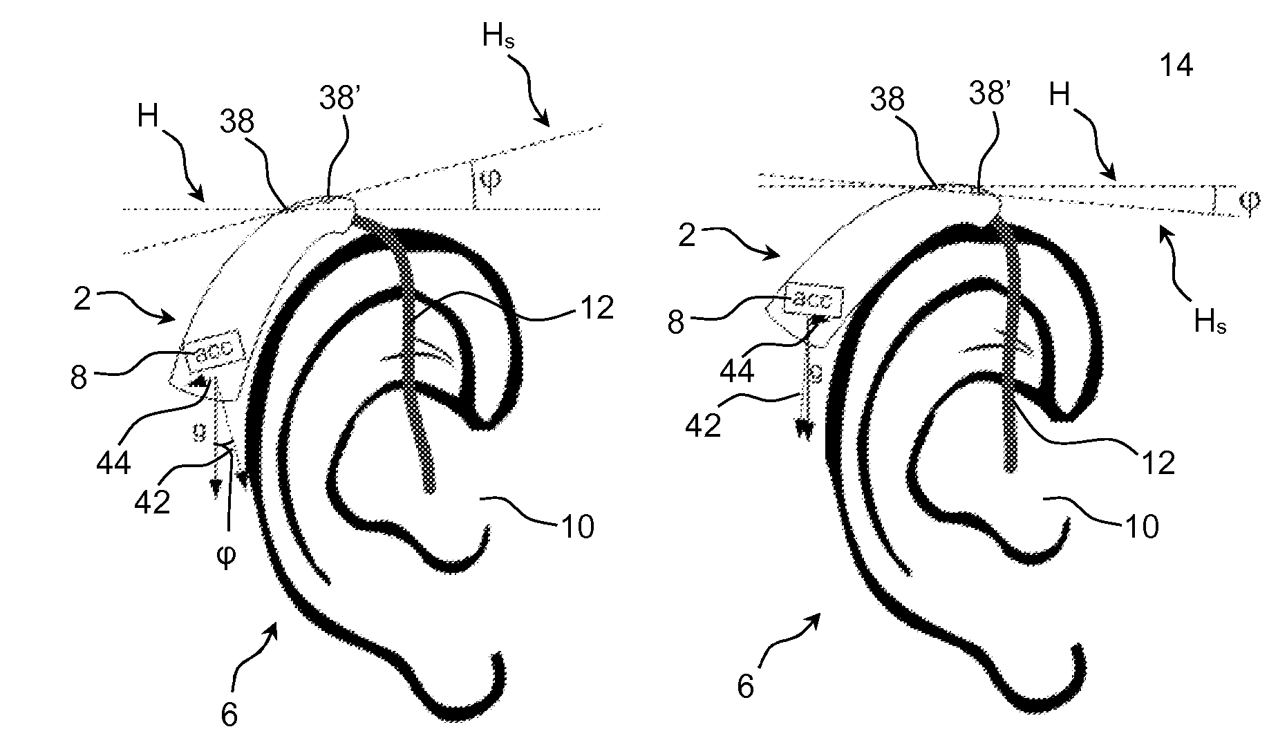
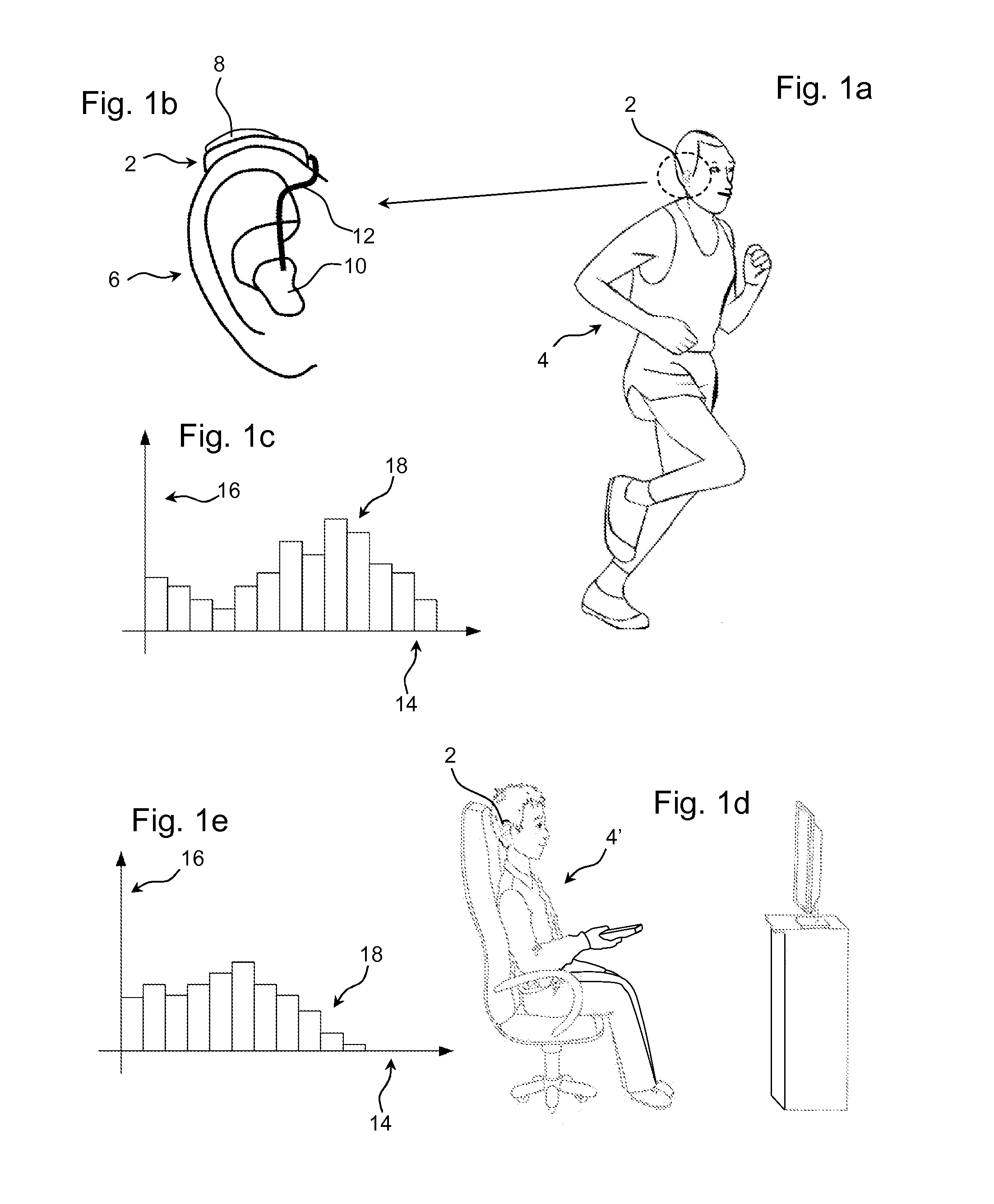
The present patent aims to provide a hearing aid device that can continuously and automatically collect information about the user's physical activity and head movement. This information can be used to optimize a noise reduction system of the hearing aid device. Additionally, the device can detect if the user is moving or turning their head.

Problems solved by technology

Such optimization may be carried out by fitting the hearing aid device on the basis of a number of individual parameters, however, some parameters are difficult to access and quantify.

Method used


Image

  • Hearing aid device comprising a sensor member
  • Hearing aid device comprising a sensor member
  • Hearing aid device comprising a sensor member

Examples


example 1

[0279]How to Measure Pitch, Yaw and Roll using a Movement Sensor:

[0280]Pitch, yaw and roll represent angles of rotation around respective orthogonal axes of a center of mass of an aircraft. In the following, these terms are used for a head of a user of a hearing aid device or a binaural hearing aid system comprising left and right hearing aid devices adapted for being located at or in left and right ears of a user respectively.

[0281]A definition of the rotational movement parameters pitch, yaw and roll relative to the x, y and z axis of an orthogonal coordinate system is illustrated in the left graph of FIG. 11a. Roll is defined as a rotation around the x-axis. Pitch is defined as a rotation around the y-axis. Yaw is defined as a rotation around the z-axis. The corresponding parameters are exemplified relative to a head of a user in the right graph of FIG. 11a.

[0282]Pitch is defined as a rotation of the head around the x-axis. Can be measured by either a single or a pair of hearing...

example 2

[0288]This example deals with achieving a higher accuracy for linear head movement estimates using two or more accelerometers. If the acceleration measured in the same geometric plane by a pair or more accelerometers are averaged, the precision increases and unwanted rotational information can be removed. The example shown in FIG. 12b becomes: a1x=alin+arot and a2x=alin−arot, if the point of rotation is centered. Adding the two provides: a1x+a2x=(alin+arot)+(alin−arot)=2alin, and hence: alin=(a1x+a2x) / 2. Further, the precision is improved by 3 dB.

example 3

[0289]This example deals with estimating the distance between the hearing aids. If at least one accelerometer and one gyroscope are present (either in one hearing aid or in a pair), it is possible to estimate the distance from the center of rotation to the sensors. The gyroscope will provide the angular velocity ωg and the accelerometer provides aa=rωg2. Solving for radius r gives:

r=aaωg2.

Assuming that the center of rotation is following a normal distribution it is possible to estimate the radius and so the distance between the hearing aids (2×radius) by averaging a large number of radius values r.


PUM


Abstract

A hearing aid device is disclosed. The hearing aid device comprises means to improve, augment and / or protect the hearing capability of a user by receiving acoustic signals from the surroundings of the user, generating corresponding audio signals, possibly modifying the audio signals and providing the possibly modified audio signals as audible signals to at least one of the user's ears. The hearing aid device comprises a sensor member for detecting the movement and / or acceleration and / or orientation (or spatial position) of the hearing aid device. The hearing aid device comprises at least two hearing aid microphones and a control unit for determining the position or a deviation from an intended position of the hearing aid device or hearing aid microphones. The hearing aid device is configured to compensate for a possible dislocation of the hearing aid microphones.

Description

FIELD OF INVENTION[0001]The present disclosure generally relates to a hearing aid device comprising a sensor member. The disclosure more particularly relates to a hearing aid device comprising a sensor member for detecting the movement and / or acceleration and / or orientation (or spatial position) of the hearing aid device. The disclosure also relates to a hearing aid system comprising a) two hearing aid devices and / or b) at least one hearing aid device and an auxiliary device the hearing aid device(s) comprising a sensor member for detecting the movement and / or acceleration and / or orientation (or spatial position) of the hearing aid device.PRIOR ART[0002]In the field of hearing aid devices there is an increasing awareness towards individual adaptation of the hearing aid settings in order to provide wearers with an optimum sound experience. All hearing aid producers aim for providing hearing aid devices that are capable of learning the wearer's individual preferences so that the heari...

Claims


Application Information

Patent Timeline
IPC IPC(8): H04R25/00
CPCH04R2225/63H04R25/65G01C9/00H04R1/1041H04R25/407H04R25/505H04R2225/41H04R2225/55H04R1/406H04R2430/20H04R2225/0213H04R25/305H04R25/453H04R2225/31H04R2460/03
Inventor PEDERSEN, MICHAEL SYSKINDMOLLER, KENNETH RUESKOVPETERSEN, SVEND OSCARKIEMER, NIELS STUBAGERNIELSEN, JESPER KOFOEDOHL, BJORNELMLUND, MARIANNE KLEISTCARVALHO, KARINBENDSEN, HENRIKPEDERSEN, REGIN KOPPBURGER, CHRISTIAN C.MUNK, STEEN MICHAELCHRISTOPHERSEN, MORTENPEDERSEN, JULIE HEFTINGWESTERG RD, BOOXENBOLL, MARIA
Owner OTICON
Learn More