Epilating device

a technology of epilating device and epilating head, which is applied in the direction of hair cleaning, hair equipment, hair singing, etc., can solve the problems of inconvenient shoulder width, and achieve the effect of preventing wobbling motion and compact design

Inactive Publication Date: 2015-08-20
KONINKLJIJKE PHILIPS NV
View PDF3 Cites 6 Cited by
  • Summary
  • Abstract
  • Description
  • Claims
  • Application Information

AI Technical Summary

Benefits of technology

[0008]The unitary support element may be formed of any appropriate material, including moulded plastics and composites. In a preferred embodiment, the mounting element comprises a metal plate provided with a locating structure for supporting the first end of the tweezer portion. The locating structures may be provided by apertures, blind holes, pins or any other suitable structure for locating the tweezer portion according to its required mode of operation. These may also be integrally formed from the same sheet although additional elements may be added as required. Such a support element formed of relatively thin sheet metal can reduce the overall width of the shoulder regions, leading to a slim design that is easy to use in restricted regions. Since the spring element is unitary with the mounting element, the material used should be sufficiently resilient to perform the spring function required by the tweezer portion. In certain embodiments, this may require a spring force of around 10 N and a movement range of 1 mm or more. The skilled person will be well aware of the variations required in these values and will be able to dimension the spring element and support element accordingly.
[0010]According to one preferred embodiment of the invention the drive element comprises a gear wheel mounted between the mounting element and the bearing element at the first end of the tweezer portion. The gear wheel may be mounted to the tweezer portion for rotation therewith and may be engaged by another gear driven from a suitable drive motor. The gear wheel may be smaller in diameter than the bearing element and locate within the latter, allowing for a more compact design. Most preferably, the gear wheel bears against the mounting element to guide its rotation and prevent wobbling motion that may be transmitted from the tweezer portion.

Problems solved by technology

Although the known devices may operate adequately in most circumstances, for accessing narrow regions, the width of the shoulders can be inconvenient.

Method used


Image

  • Epilating device
  • Epilating device
  • Epilating device

Examples


first embodiment

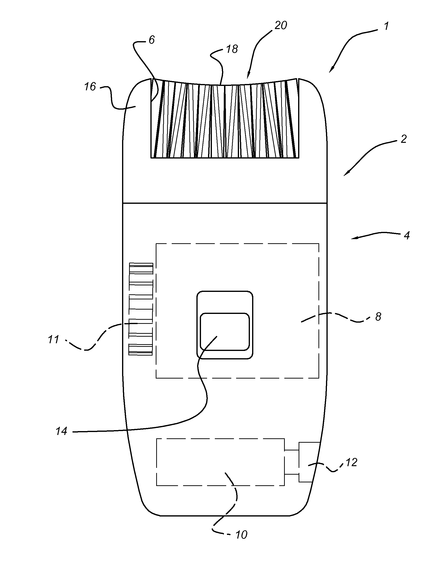
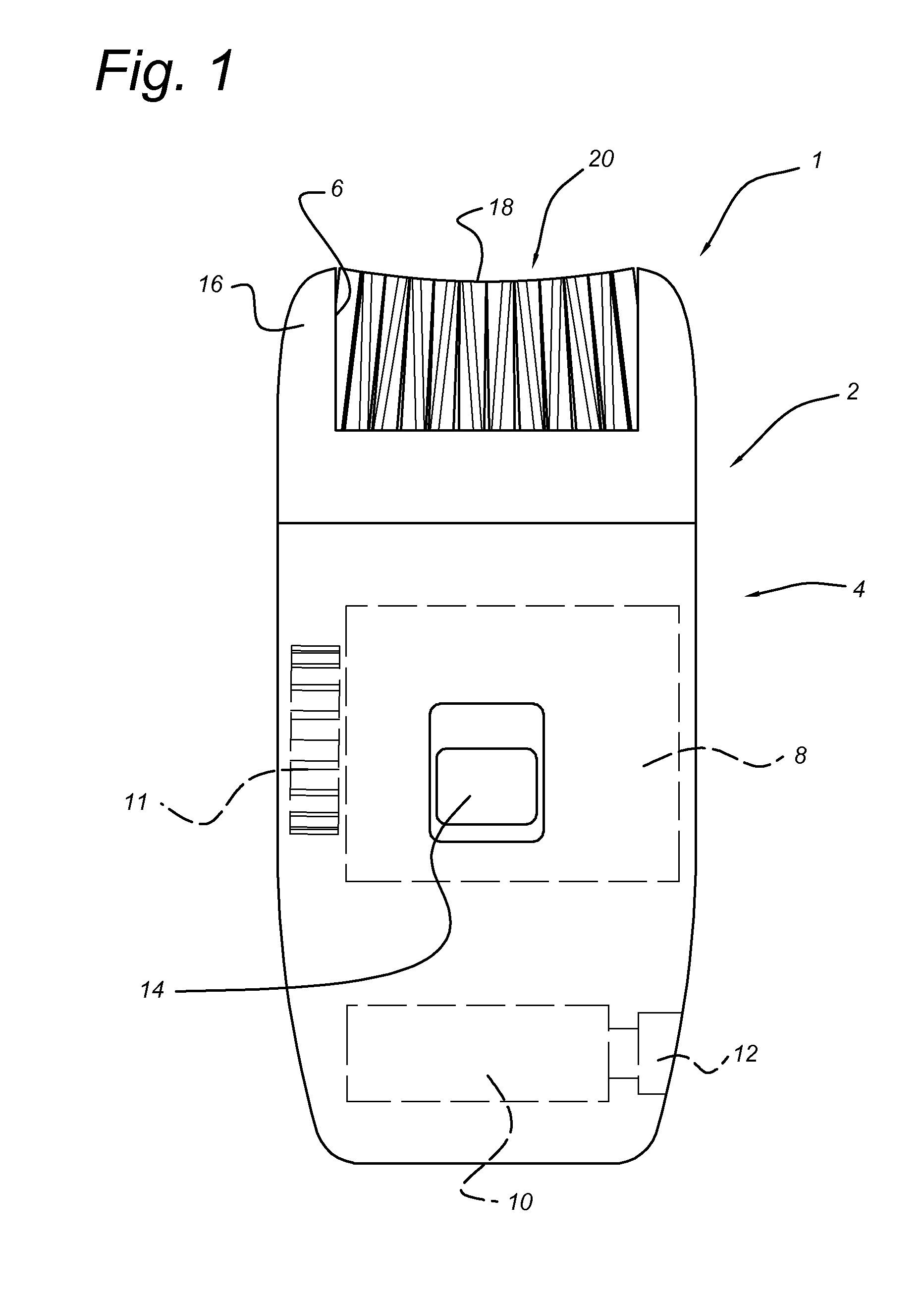
[0028]FIG. 1 shows a perspective view of an epilating device 1 according to the invention. The epilating device 1 comprises a head portion 2 and a motor portion 4, which engage together. The head portion 2 has an access opening 6 in its forward surface providing access to a pinching region 18 of a tweezer portion 20, which will be described in further detail below. The opening 6 is delimited on either side by shoulders 16. The tweezer portion 20 and the shoulders 16 together define the overall width of the epilating device.

[0029]The motor portion 4 houses a motor 8 having an output gear 11 and a rechargeable power supply 10, which can be charged through a jack 12. An on-off switch 14 is provided on the front face. The motor portion 4 has an ergonomic form for use as a handle.

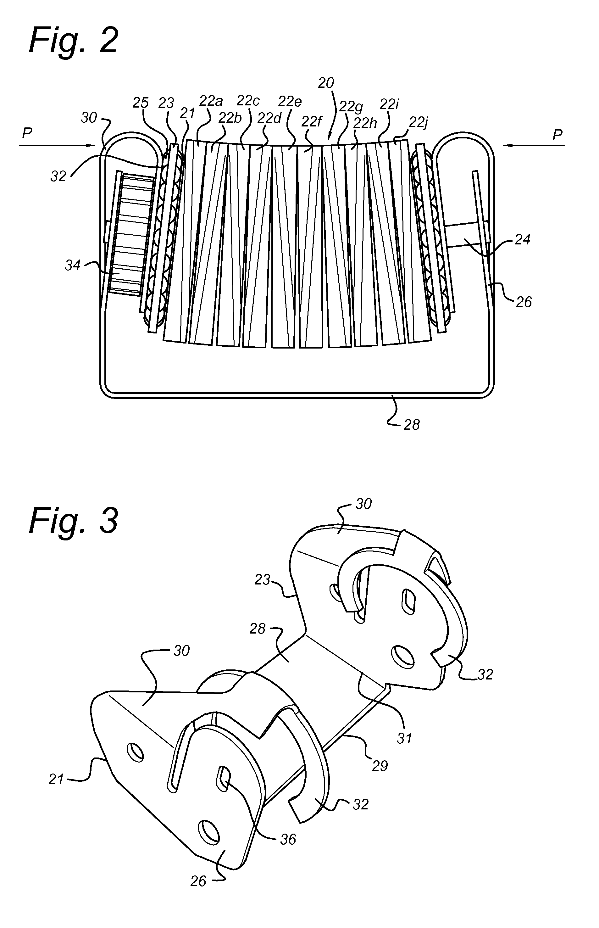
[0030]FIG. 2 shows in front elevation a portion of the epilating device 1 with the head portion 2 removed. As can be seen in FIG. 2, the tweezer portion 20 comprises a plurality of disks 22A-22J mounted together...

second embodiment

[0036]According to FIG. 6, a yoke 228 supports a tweezer portion 220. The yoke 228 is asymmetric and otherwise identical to that of FIG. 4, comprising a washer 232 and spring arm 230 at one side only. At the other side of the yoke 228, the upstanding leg 226 is generally flat and provided with a locating hole 236 for receiving a shaft 224 of the tweezer portion 220. The washer 232 and upstanding leg 226 are angled with respect to each other towards a pinching region 218.

[0037]In this embodiment, the tweezer portion 220 comprises an inner body 240 and an outer body 242 arranged to rotate together about the shaft 224 under the action of a cog 234. Actuating rods 244 extend through channels 246 within the inner body 240 and have cam surfaces 248 at their outermost extremities. Return springs 250 within the channels 246 bias the rods outwards such that the cam surfaces engage with washers 232 and upstanding leg 226 respectively. The outer body 242 is formed in three sections 242 A, B, C...


PUM


Abstract

An epilating device (1) removes hair from a user by pinching, pulling and releasing the hairs. The epilating device (1) has a tweezer portion (20) having an axis and being mounted to rotate about its axis during use, the tweezer portion (20) defining at least one pinching region (18) at its circumference in which hairs may be grasped by tweezer elements(22). A mounting element supports the axis of the tweezer portion such that the tweezer portion can rotate with respect to the mounting element and a spring element (30) is arranged to induce a pinching force in the tweezer elements at the pinching region (18). The pinching force induces pinching of the hairs at the pinching region (18). A bearing element (23) is arranged to transmit the pinching force to the rotating tweezer portion (20) and a drive element is arranged to apply rotational motion to rotate the tweezer portion about its axis with respect to the mounting element. The mounting element (20), spring element (30) and bearing element are formed as a single unitary support element.

Description

BACKGROUND OF THE INVENTION[0001]1. Field of the Invention[0002]The present invention relates to epilating devices and in particular to an improved epilating head construction having narrow support shoulders.[0003]2. Description of the Related Art[0004]Epilating devices of many different types are known for the purpose of removing unwanted hair from various regions of a user's body. The principles of operation vary greatly but amongst these devices, a sizeable subgroup operates through the use of rotating tweezer-mechanisms which seize hairs and actively extract them from the skin / follicle. As the tweezer rotates further it releases the hair. In the present context, the term “tweezers” is used to denote an arrangement that is capable of opening and closing to grip and extract a hair or hairs.[0005]One of the earliest devices of this type is the Epilady™ device, which uses the rotation of a coil spring to capture and release hairs. Another device is disclosed in EP532106B1. That devi...

Claims


Application Information

Patent Timeline
Patent Type & Authority Applications(United States)
IPC IPC(8): A45D26/00
CPCA45D26/0028A45D26/0066A45D2026/008
Inventor HETBRINK, INGRIDPUTZER, ARTHUR
Owner KONINKLJIJKE PHILIPS NV
Why Eureka
Try Eureka