Lateral plate

Active Publication Date: 2015-08-20
MASTROS INNOVATIONS LLC
View PDF3 Cites 6 Cited by
  • Summary
  • Abstract
  • Description
  • Claims
  • Application Information

AI Technical Summary

Benefits of technology

[0008]According to another aspect of the invention, a bone plate system is provided. The bone plate system includes a plate having at least one hole configured to receive a bone fastener for attaching the plate to bone. The plate has a top surface and a bottom surface interconnected by a side surface. The bone plate system includes at least one fastener having a head at a proximal end and a bone-engaging portion distal to the head. The bone-engaging portion extends to a distal end. The fastener is disposed inside at least one hole of the plate such that the head is substantially seated inside the hole and the bone-engaging portion extends from the bottom surface of the plate. The bone plate system includes a locking system connected to the plate. The locking system is configured to include an unlocked configuration, a first locked configuration and a second locked configuration. In the unlocked configuration, the fastener is removable from the hole in a proximal direction and permitted to angulate with respect to the plate. In the first locked configuration, the fastener is prevented from being removed from the hole in a proximal direction and is permitted to angulate with respect to the plate. In the second locked configuration, the angulation of the fastener with respect to the plate is fixed and the fastener is prevented from being removed from the hole in a proximal direction.
[0009]According to another aspect of the invention, a bone plate system is provided. The bone plate system includes a first plate having at least one hole configured to receive a bone fastener. The first plate has a top surface and a bottom surface interconnected by a side surface. The first plate has a distal extension with an aperture extending between the top surface and the bottom surface. The

Problems solved by technology

Over time, the interface between the screws and the bone may present some problems of stability.
Also,

Method used


Image

  • Lateral plate
  • Lateral plate
  • Lateral plate

Examples


Example

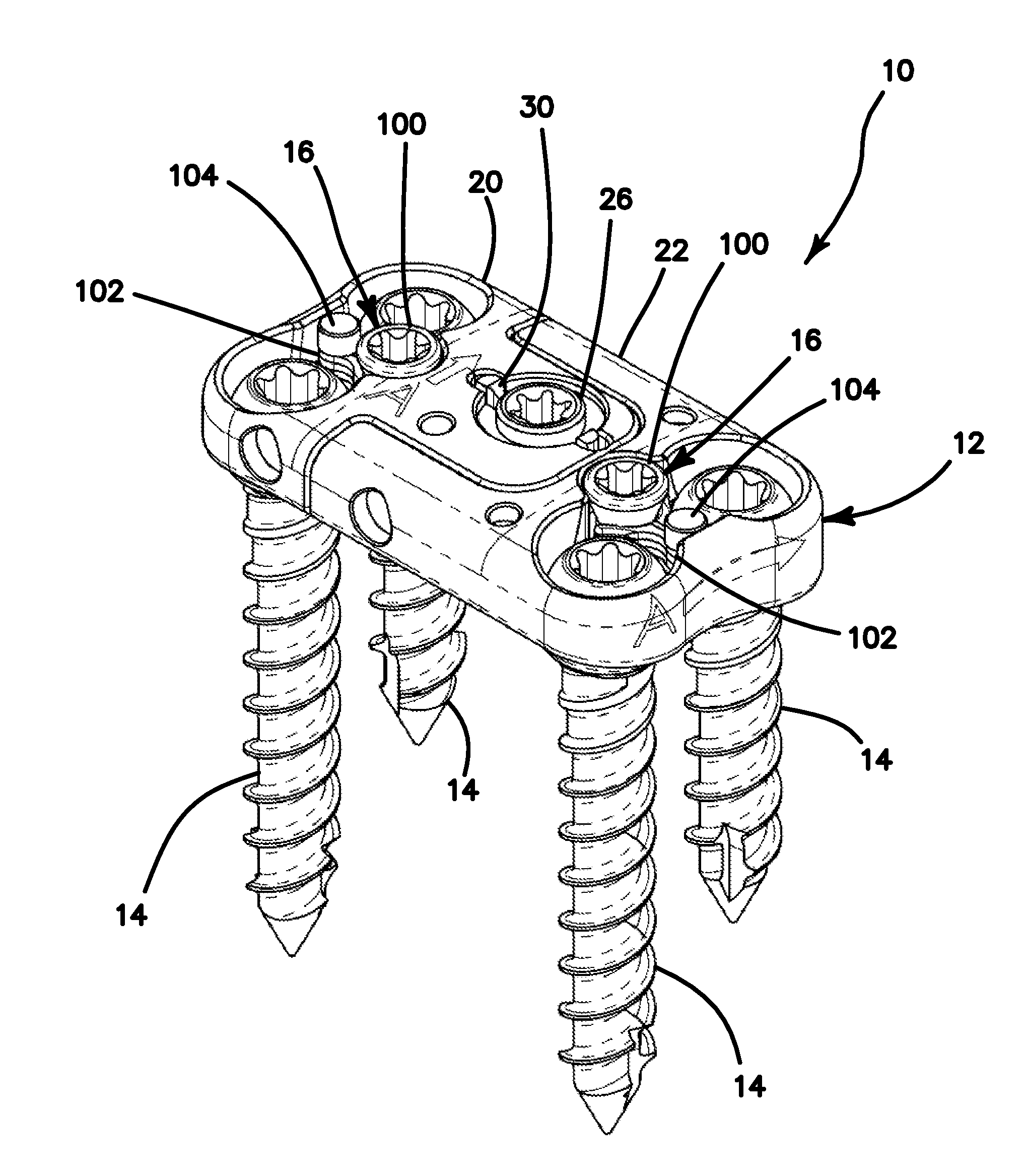
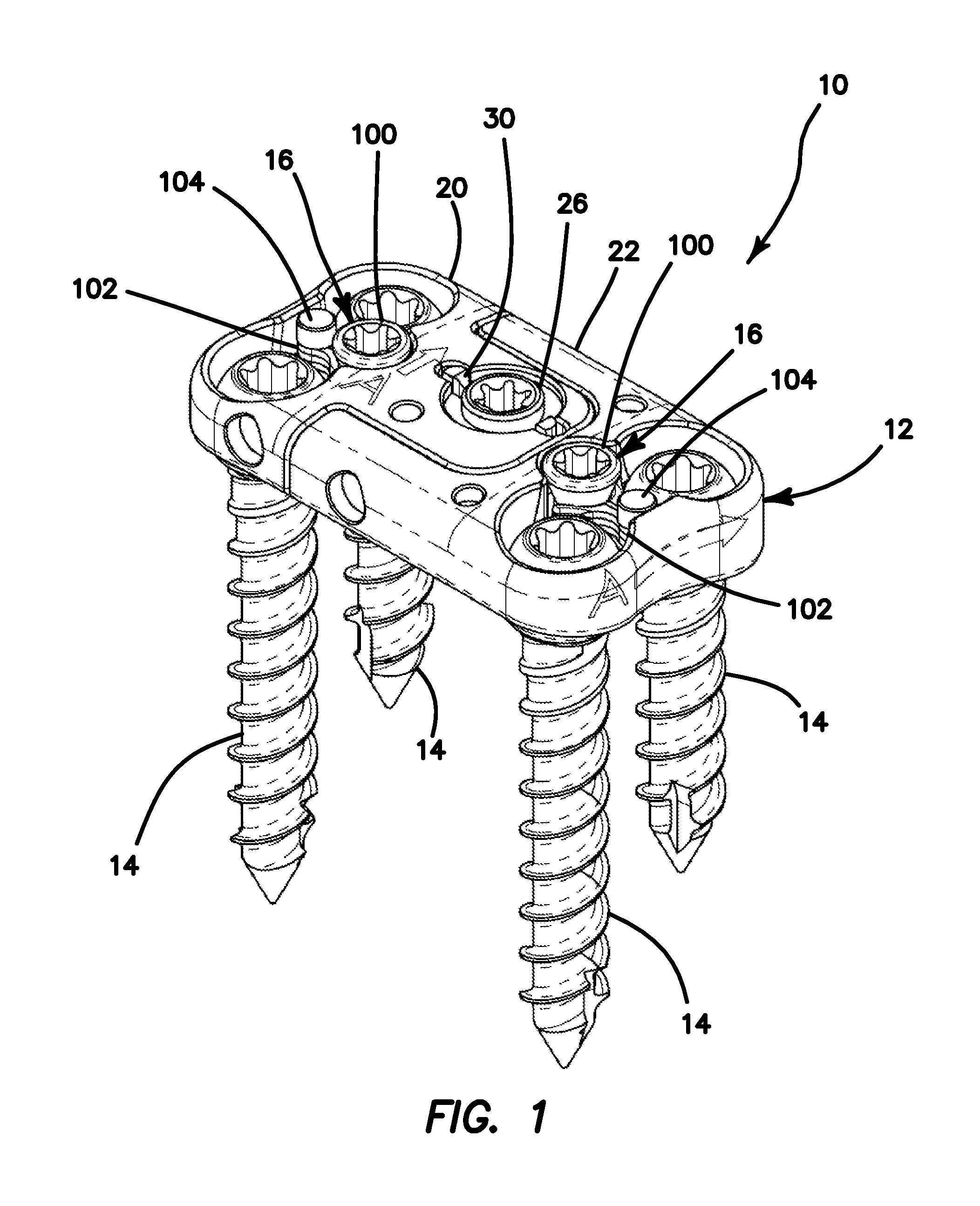
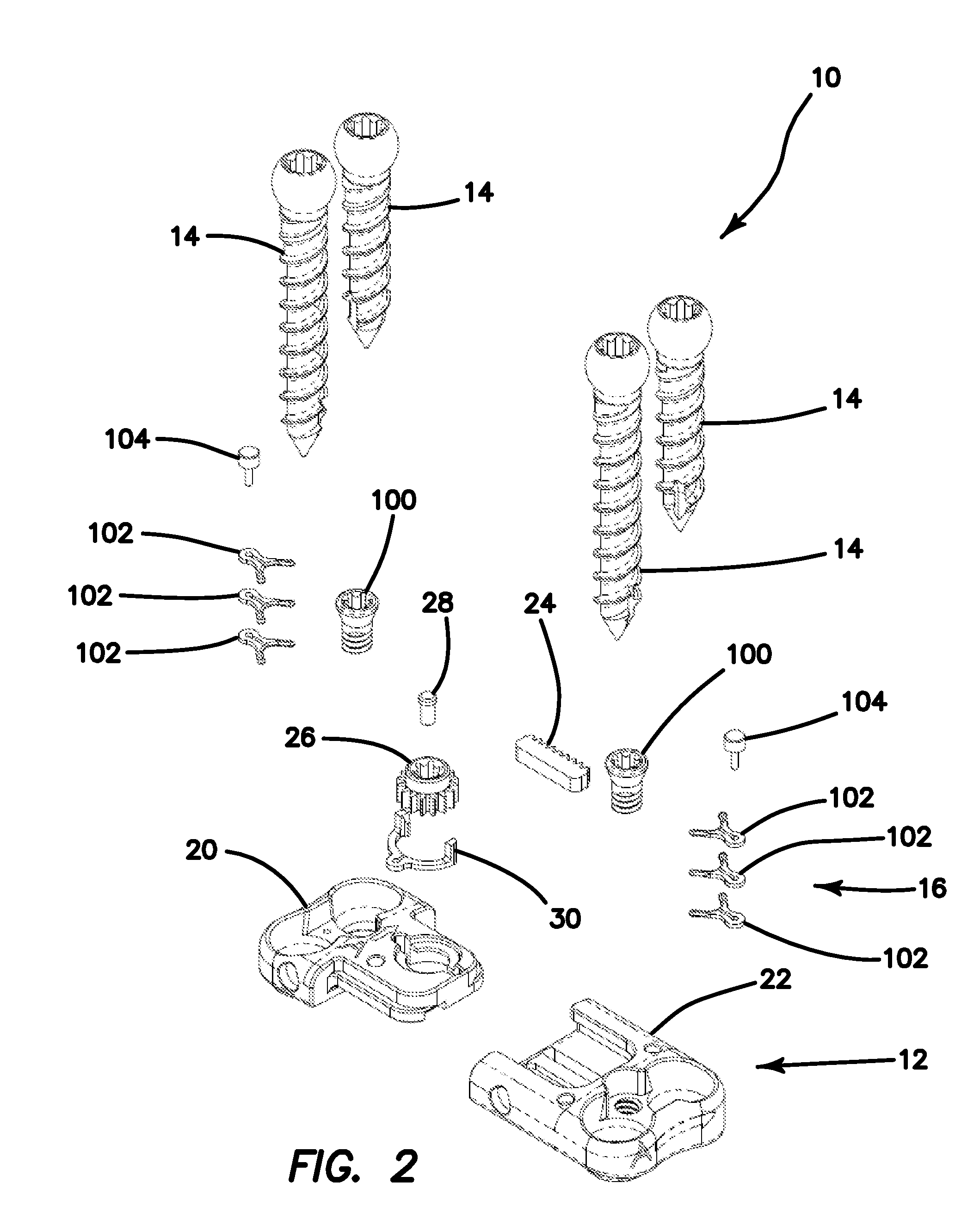
[0050]FIGS. 1-5 depict a bone plate system 10 according to one variation of the invention that may be used to stabilize or fuse vertebral bodies of the spine to allow fusion by holding the vertebral bodies in proper alignment, and thus allowing the spine to heal. The bone plate system 10 that is shown in FIGS. 1-5 is a single-level bone fixation plate that is configured to span across a single disc and fixate two vertebrae of the spine although the bone plate system 10 may be a two-level or any multilevel bone plate spanning two or more vertebral bodies. The bone plate system 10 is attachable to the lateral aspect of the two or more vertebrae; however, the invention is not so limited and the plate can be employed in anterior, posterior, antero-lateral or oblique positions with respect to two or more vertebrae. The plate can be employed for spinal stabilization in conjunction with anterior or posterior fusion procedures for placement of the fusion construct in a disc space between ve...


PUM


Abstract

A bone plate system is provided. The system includes two or more fastener locks stacked on top of each other and located between two holes in a plate adapted to receive bone fasteners. An actuator is provided between the locks. As the actuator is advanced, the locks are moved sequentially into position, firstly, to prevent one or more bone fasteners from backing out of the plate while permitting the fasteners to angulate and, secondly, to lock the angulation of the bone fasteners while still providing back out protection in situ. An expandable bone plate having a top plate interconnected to a bottom plate by a rack and pinion is provided. The rotation of the pinion with a driver lengthens or shortens the plate incrementally for custom length adjustment. The length is fixed in position with the simple removal of the driver and no further step is required to lock the plate length.

Description

FIELD OF THE INVENTION[0001]This invention relates to bone fixation plates and, more particularly, to fixation plates for the spine that are expandable and to fixation plates that resist the backing out of associated bone fasteners.BACKGROUND OF THE INVENTION[0002]Spinal bone plates are used for a variety of conditions to immobilize, stabilize or align cervical vertebrae. For example, after a spinal fusion surgery, bone plates are used to add strength and rigidity to the adjoined vertebrae. Also, plates secure vertebrae together where an intervening vertebra has been removed or replaced. In other cases, spinal bone plates are used to correct instability in the spine caused by trauma, tumors, advanced degenerative discs, infection or congenital or acquired deformities.[0003]A typical spinal bone plate includes an elongated rectangular plate that spans the distance between two or more vertebrae. The plate is curved to match the natural curvature of the spine at the location to which i...

Claims


Application Information

Patent Timeline
IPC IPC(8): A61B17/70
CPCA61B17/8009A61B17/8023A61B17/8047A61B17/7059A61B17/7058A61B17/86
Inventor ALTARAC, MOTIREGLOS, JOEYSCHNEIER, MICHAELGROSSMAN, BRIAN STUARTDAVIS, MICHAELLEIBERT, DALE LAWRENCESTEPHANI, JOHN FREDRICK
Owner MASTROS INNOVATIONS LLC
Why Eureka
Try Eureka