Screw and rod fixation system

a fixation system and screw technology, applied in the field of screw and rod fixation assemblies, can solve the problems of compromising correction, fixing points that cannot be aligned, and the doctor is unable to introduce the rod into all of the fixation points or bring,

a fixation system and screw technology, applied in the field of screw and rod fixation assemblies, can solve the problems of compromising correction, fixing points that cannot be aligned, and the doctor is unable to introduce the rod into all of the fixation points or bring,

US20150230836A1Inactive Publication Date: 2015-08-20COCHRAN SCOTT

Image

  • Screw and rod fixation system
  • Screw and rod fixation system
  • Screw and rod fixation system

Examples


Embodiment Construction

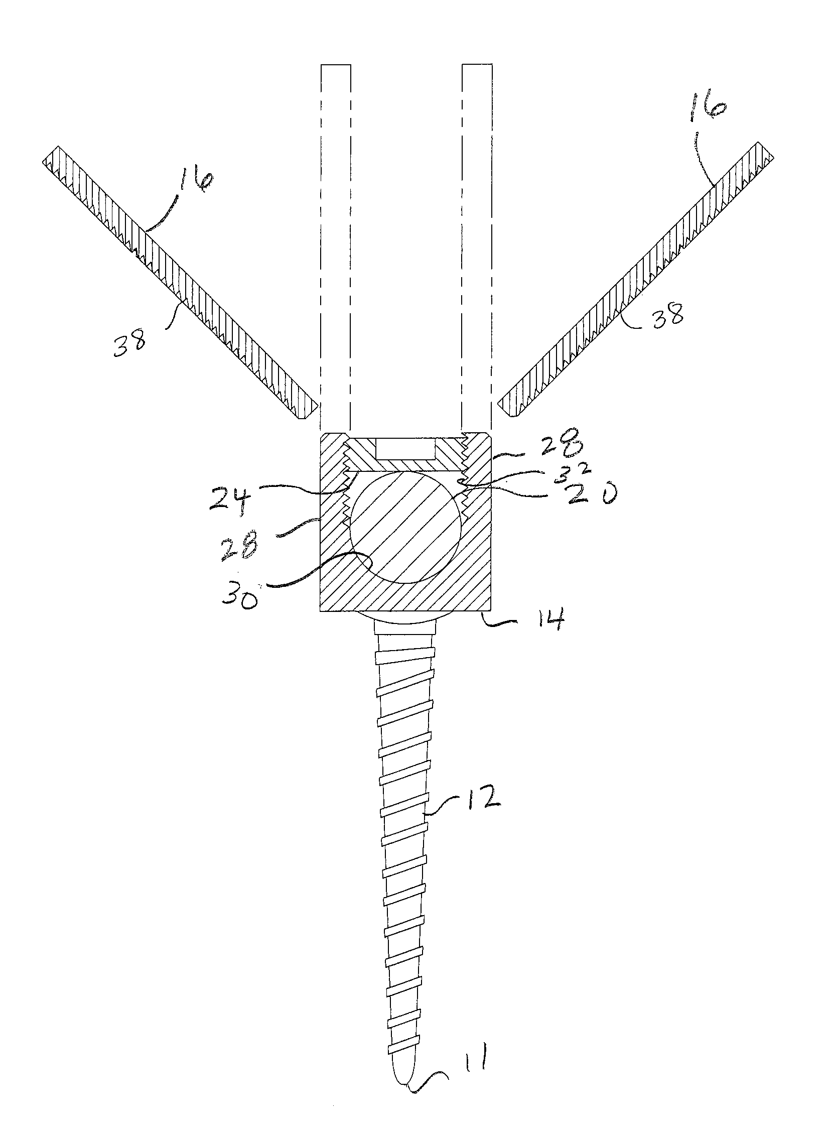
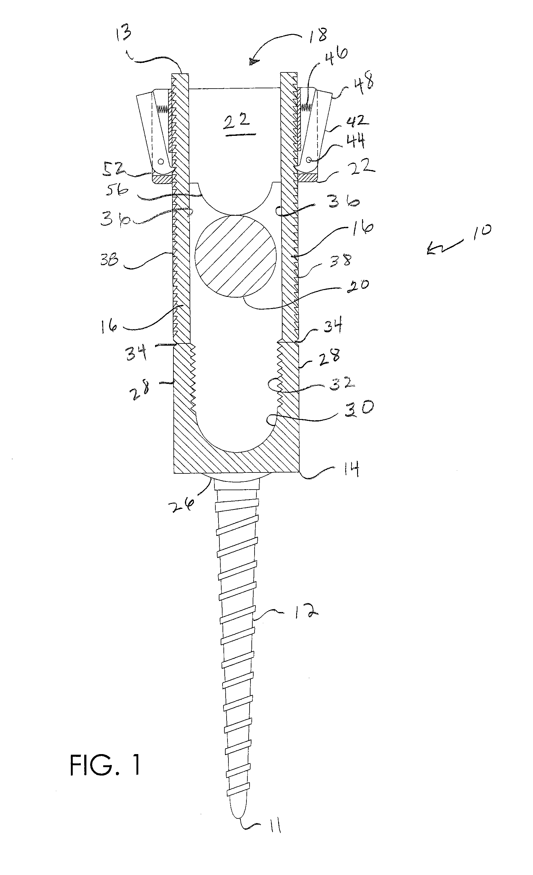
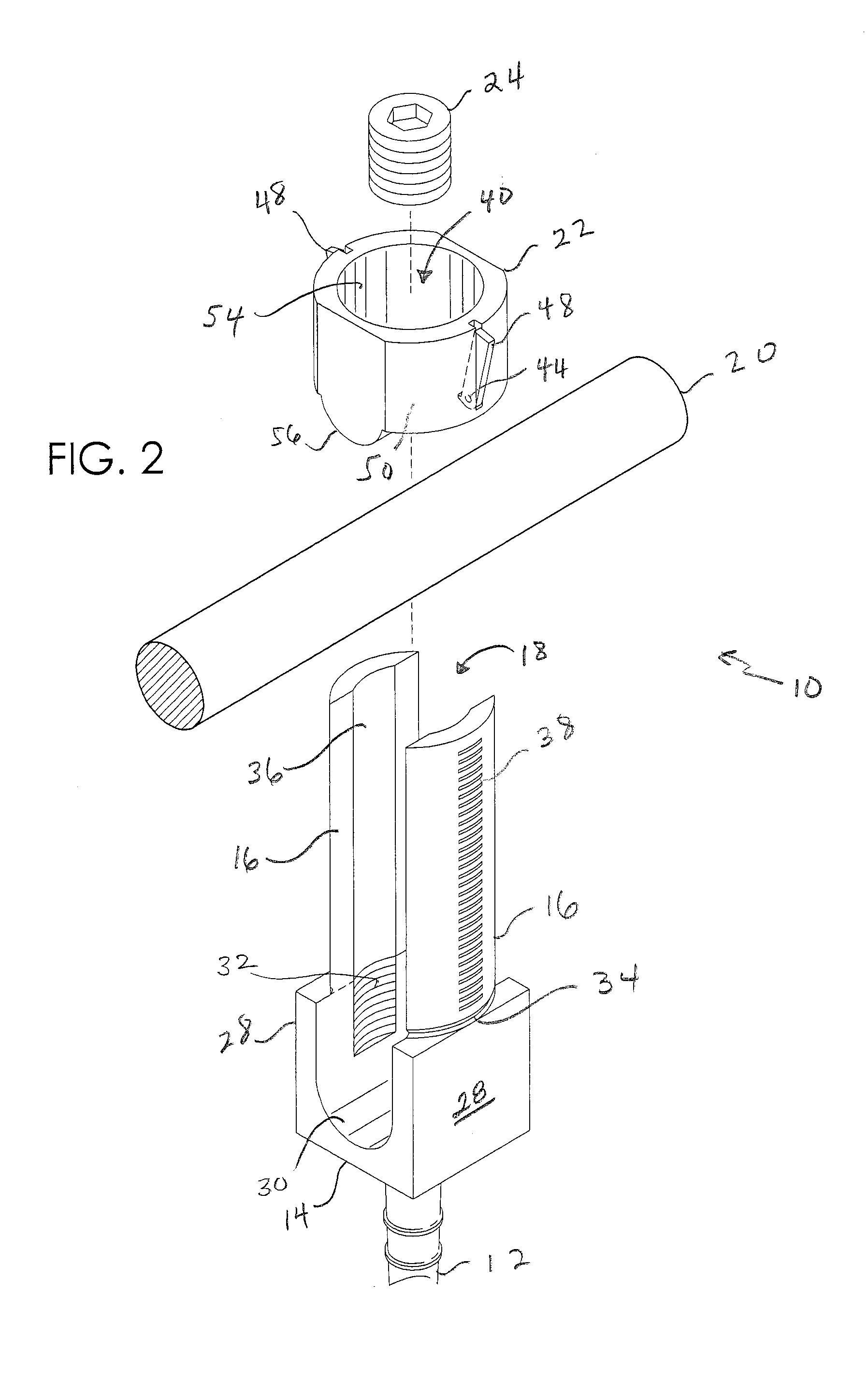
[0033]FIGS. 1 through 13 illustrate a screw and rod fixation assembly 10 and various parts thereof in accordance with a preferred embodiment of the present invention. Generally, assembly 10 includes a distal end 11, a pedicle screw 12 having a screw head 14, a proximal end 13, a pair of opposing extension tabs 16 detachably coupled to screw head 14, a rod receiving slot 18 defined between extension tabs 16, a rod 20 slideably received within slot 18, a ratchet collar 22 pressed against rod 20 and coupled to tabs 16 in a manner allowing movement of collar 22 distally along tabs 16 while preventing movement thereof proximally and a set screw 24 for locking rod 20 within screw head 14.

[0034]More particularly, referring to FIGS. 1 and 2, screw 12 can be any size, shape or design as is known to those of skill in the art for anchoring to bone. In the preferred embodiment, screw 12 is a monoaxial pedicle screw and is therefore integrally formed with screw head 14 which is axially aligned w...


PUM

PropertyMeasurementUnit
forceaaaaaaaaaa
flexibleaaaaaaaaaa
shapeaaaaaaaaaa

Abstract

A pedicle screw and rod fixation assembly including a pair of opposing tabs having a proximal end and a distal end, the pair of opposing tabs being coupled to one another about the distal end thereof by a screw head member, a decoupling mechanism for decoupling the pair of opposing tabs from the screw head member, a rod receiving slot between the pair of opposing tabs, and a sliding member configured for coupling to the pair of opposing tabs. The sliding member and the pair of opposing tabs are configured for allowing movement of the sliding member distally along the pair of opposing tabs and preventing movement of the sliding member proximally along the pair of opposing tabs.

Description

RELATED APPLICATIONS[0001]This application is a continuation of U.S. patent application Ser. No. 13 / 080,482, filed on Apr. 5, 2011 and titled, “Screw and Rod Fixation System,” the entire contents of which are incorporated herein by reference.FIELD OF THE INVENTION[0002]The present invention relates to spinal implants. More particularly, the present invention relates to screw fixation assemblies for use with bone fixation systems.BACKGROUND OF THE INVENTION[0003]Spinal deformity surgery is a complex technical procedure that can involve numerous implants and techniques to achieve a straightening of the spine in three dimensions. There is a sagital plane that may contain an increased or decreased lordosis or kyphosis, a coronal plane that may contain a left / right curvature of the spine and an axial plane that may contain a rotational deformity. All three planes must be addressed if a result that leaves the patient functional and provides acceptable cosmesis is to be achieved.[0004]Curr...

Claims


Application Information

Patent Timeline
20 Aug 2015
Publication
US20150230836A1
IPC
A61B17/70
CPC
A61B17/7086; A61B2017/00477; A61B2017/00407; A61B17/7032; A61B2090/037; Y10T29/49826; A61B17/86
Inventors
COCHRAN, SCOTT