
Y-lock tracheal stent system and metod of use

Active Publication Date: 2015-08-20
NEW YORK UNIVERSITY
View PDF1 Cites 4 Cited by
  • Summary
  • Abstract
  • Description
  • Claims
  • Application Information

AI Technical Summary

Benefits of technology

The medical stent is designed to decrease the size of the anchor loops when two forces are applied parallel to the spines. This reduces the cross-sectional area of the stent, making it easier to insert and position.

Problems solved by technology

Externally induced physical trauma can cause deformation of the structure of the larynx thereby interfering with the proper functioning of the vocal folds.
Vocal cord paresis is weakness of one or both vocal folds that can greatly impact daily life.

Method used


Image

  • Y-lock tracheal stent system and metod of use
  • Y-lock tracheal stent system and metod of use
  • Y-lock tracheal stent system and metod of use

Examples


Embodiment Construction

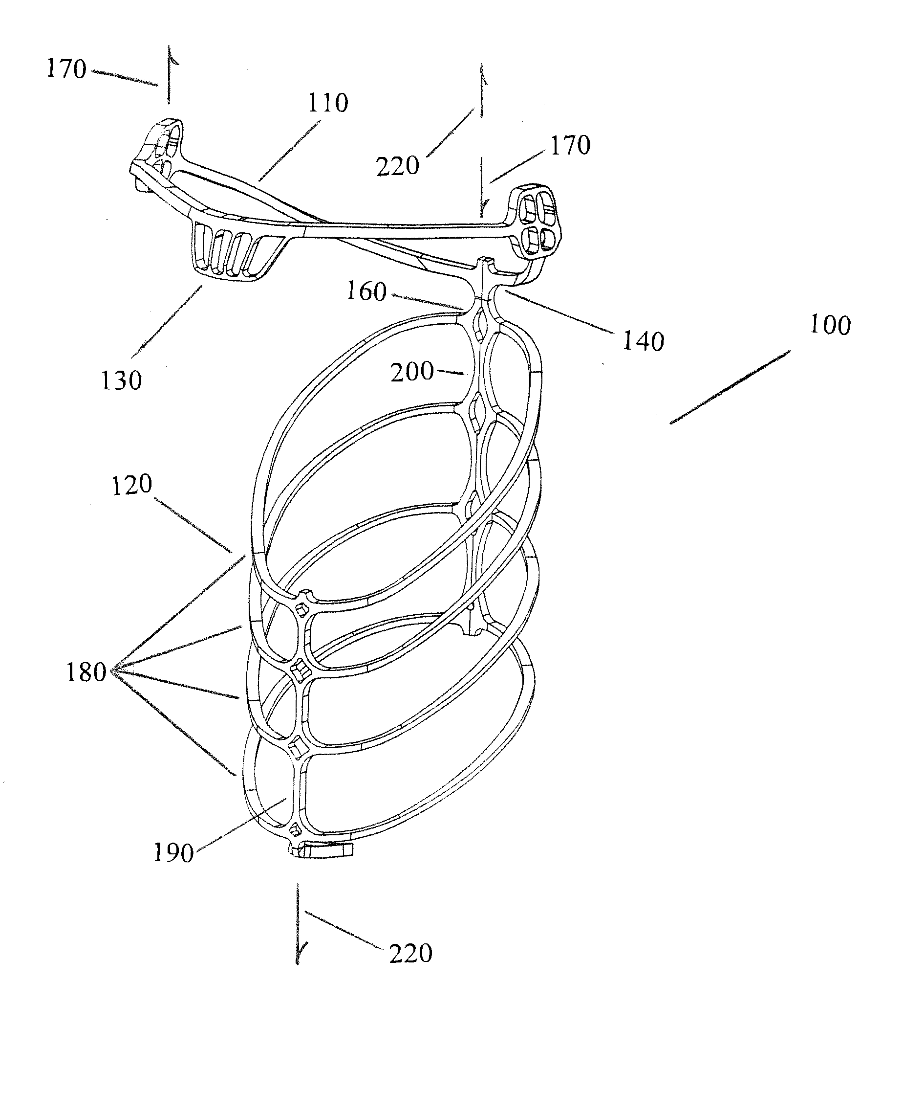
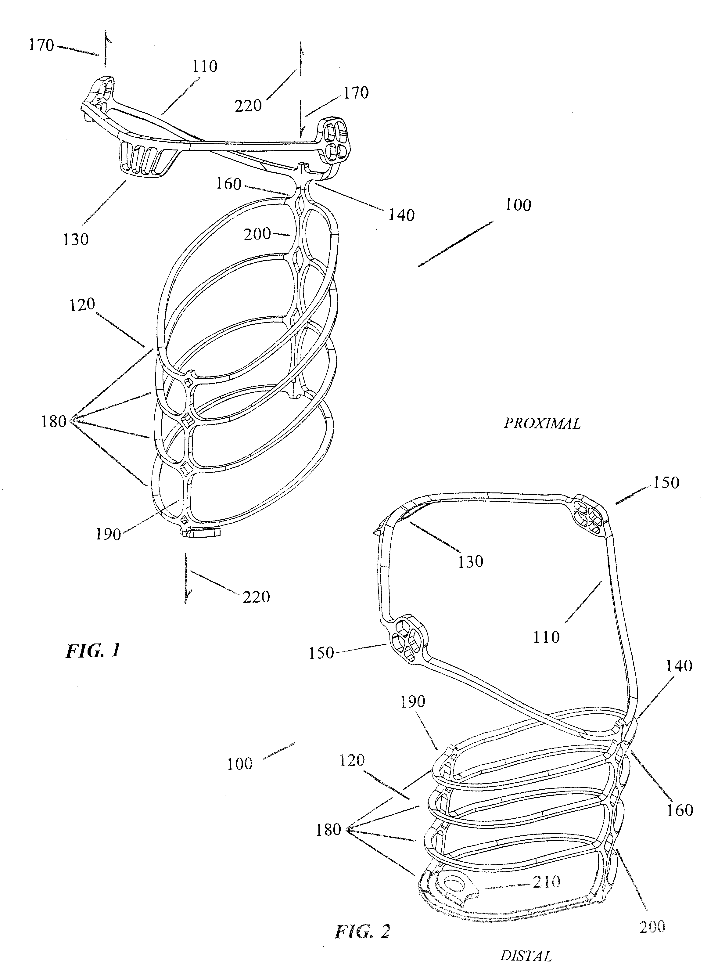
[0037]A first non-limiting embodiment of a stent 100, suitable for arytenoid abduction, is presented in the anterior perspective in FIG. 1 and the posterior perspective in FIG. 2. While the description pertains to the treatment of the arytenoid cartilages, other non-limiting embodiments of the invention, suitable for treatment of other pathologies is envisioned, and will be obvious to those of typical expertise in the field.

[0038]The stent 100 is comprised of a Y-lock crown 110 that is resiliently connected to an anchor 120. The Y-lock crown 110 is a resilient loop sized to diagonally set within the larynx immediately above the trachea. When emplaced, the proximal extremity of the Y-lock crown 110, comprising a center contact pad 130, may be deployed to exert an upward force under the apex of the vocal folds as a result of its resiliency. The magnitude of the upward force is determined, in part, by the mechanical properties of the stent and placement of the distal extremity 140 of t...


PUM


Abstract

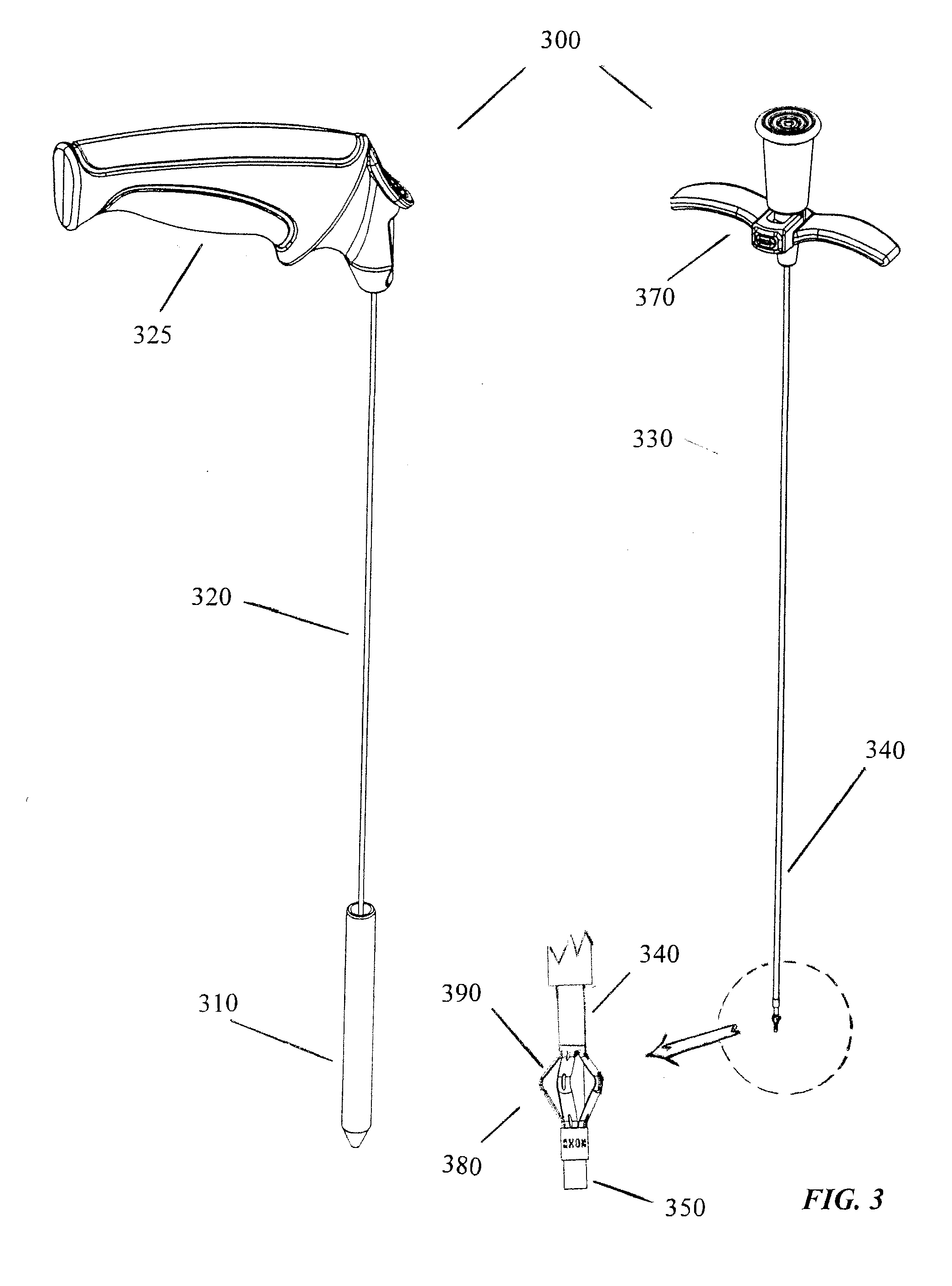
A Y-Lock tracheal stent system consisting of a stent device, for emplacement in the larynx, and a stent delivery system. A method for employing the stent delivery system to emplace the stent device.

Description

PRIORITY[0001]This non provisional patent application claims the benefit of priority from U.S. Provisional Patent Application 61 / 941,589, filed 19 Feb. 2014, and U.S. Provisional Patent Application No. 62 / 016,252, filed 24 Jun. 2014, the contents of which are hereby incorporated by reference herein in their entirety.BACKGROUND[0002]The larynx is an organ located in the human neck between the pharynx and the trachea. Nine cartilages make up the larynx including three single cartilages (epiglottic, thyroid and cricoid) and three paired cartilages (arytenoid, corniculate, and cuneiform). The larynx is further comprised of two flexible vocal folds that serve as the valve controlling the flow of air through the larynx for phonation or preventing the passage of solids and liquids to the trachea. The vocal folds are supported by the arytenoid cartilages. Muscles attached to the arytenoid cartilages control the degree of opening of the folds. Vocal fold length and tension can be controlled ...

Claims


Application Information

Patent Timeline
IPC IPC(8): A61F2/82A61F2/844A61F2/95
CPCA61F2/04A61F2002/9665A61F2230/0095A61F2/844A61F2002/046A61F2210/0014A61F2310/00023A61F2/82A61F2/95
Inventor RIINA, HOWARDWARD, ROBERTTIPPETT, JONATHANMULABDIC, FEDJA
Owner NEW YORK UNIVERSITY
Learn More